The lecture discusses the current methods used to fabricate orbital prostheses. Topics include surgical alterations during orbital exenteration that enhance the prosthetic prognosis, methods used when making orbital impressions, sculpting and margin placement, flasking, processing and coloration. The lecture concludes with a detailed discussion of the use of craniofacial implants used for retention including implant connecting bar design, the use of magnetic attachments and management of implant related complications.
Maxillofacial Prosthetics – Restoration of Orbital Defects – Course Transcript
- 1. Restoration of Orbital Defects John Beumer III DDS, MS Don Pedroche DDS, CDT Division of Advanced Prosthodontics UCLA School of Dentistry*The material in this program of instruction is protected by copyright ©. Nopart of this program of instruction may be reproduced, recorded, ortransmitted by any means, electronic,digital, photographic, mechanical, etc.or by any information storage or retrieval system, without prior permission.
- 2. Alterations at surgery to enhance the prosthetic prognosisOrbital defects v Line the orbit with skin v Avoid distortion of the eye brow v Do not close the defect with flaps v Do not retain the eyelids
- 3. Alterations at Surgery to Enhance the Prosthetic Prognosis Orbital DefectsThis orbital exenteration defect is close to ideal. The entirecontents of the orbit have been removed and the orbital wallslined with skin. However, the position of the eyebrow issomewhat distorted.
- 4. Alterations at Surgery to Enhance the Prosthetic Prognosis Orbital Defectsv Lateral facial orbital defect resurfaced with a free flap leaving sufficient space for an orbital prosthesis.v Orbital prosthesis in position.
- 5. Alterations at Surgery to Enhance the Prosthetic Prognosis Unfavorable Orbital DefectsThe lids were retained following orbital exenteration. Thereis insufficient space for an orbital prosthesis. If an orbitalprosthesis is contemplated, they should be removed.
- 6. Alterations at Surgery to Enhance the Prosthetic Prognosis Unfavorable Orbital Defects This orbital defect was filled with a flap. As a result, there is insufficient space for a prosthesis.
- 7. Alterations at Surgery to Enhance the Prosthetic Prognosis Unfavorable Orbital Defects The eyebrow has been altered in this patient making it more difficult to restore facial symmetry with an orbital prosthesis
- 8. Master ImpressionsImpressions should be made so as to avoid displacing softtissues. Impression steps: 1) Drape the patient. Apply a thin layer of Vaseline to hair bearing areas. 2) Apply a thin layer of polysulfide to the surface of the skin. 3) Apply an unfolded gauze to the surface of the polysulfide before it polymerizes.
- 9. Master Impressions Impression steps (cont’d) 4) Coast the impression and gauze with a thin layer of polysulfide adhesive 5) Apply several layers of quick set plaster to the impression. The first layer should be very thin and applied with a brush.
- 10. Master castMaster cast is made with an improved dental stone.Avoid stones with pigment, for these stones maystain the silicone prosthesis during processing.
- 11. Digital impressions Device used for phase measuring profilometry (3D photography).The process uses multiple light sources, is safe, can be employed with eyes openand takes only three seconds. The data retrieved is used to develop threedimensional images. The working models made from these images are veryaccurate, enable the recording of the contours of the defect with the head in anupright position and avoid distortion of displaceable tissues associated with the useof conventional impression techniques.
- 12. Digital impressionsDigital impressions and CAD-CAM models are very accurate butmay not be appropriate when significant undercuts need to beengaged (Courtesy of Dr. Dr. Y-min Zhao and Dr. Guofeng Wu).
- 13. Sculptingv Select a globe that matches the opposite eyev Inscribe an arrow or incorporate an equivalent marker on its under surface
- 14. SculptingPosition the globe within a wax bolus
- 15. Sculptingv Position the globe v Anterior – posterior v Vertical plane v Lateral – medialv Develop lid contoursv Refine the surface texture
- 16. Sculptingv Lid and surrounding tissue contours have been completed.
- 17. Sculptingv Prosthesis is checked from several angles. Note that because of contour deficiency on defect side, ocular imbedded in wax is slightly posterior to normal globe.v Lines of juncture are placed behind eyeglass frames.
- 18. Sculptingv Contours associated with margins of the prosthesis must be consistent with the contours of the adjacent skin Develop surface texture and try in synthetic eyelashes
- 19. Surface TextureProper surface texture for an orbital prosthesis.Note orbital skin folds are carefully reproduced.
- 20. Surface Texture Orbital defects require much more surface detailv Large orbital defect. Surface texture of suborbital area and cheek have been faithfully reproduced.v Note that texture of sculpting is slightly more prominent than skin. This is so because some detail is lost during processing and extrinsic coloration.
- 21. Surface Texturev Ideal orbital exenteration defect. Defect is lined with skin, eyebrow is in reasonable position and adjacent facial contours are not distorted.v Orbital prosthesis in position. The globe is properly positioned, the lid contours are excellent as is the coloration.v What is lacking in this prosthesis? v Sub orbital skin texture has not been reproduced
- 22. Form and Symmetryv Maxillectomy-orbital exenteration defect. Note deficient cheek contours.v Orbital prosthesis in position. Symmetry is restored in orbital region but not in cheek. The contour of zygomatic-malar area was not restored. Cheek portion was blended with existing cheek contours.
- 23. Form and Symmetryv Note how eyeglass frames and shadows cast by them help camouflage the defect and the prosthesis.
- 24. FlaskingWax pattern sealed to master cast.
- 25. FlaskingWax flowed into desired undercuts and support areas througha hole made in back of model. Stone will be poured into thisopening during first stage of flasking.
- 26. FlaskingFirst stage of flasking is completed.
- 27. ProcessingOcular is secured.
- 28. Processing Silicone mixed to match base shade selected and injected into mold and allowed to polymerize.
- 29. DeliveryEyelashes are tucked under the lid Note how the eye glass frames hide the margins
- 30. Completed Prosthesis v The eye glass frames help to hide the margins of orbital prostheses v In this orbital prosthesis the surface texture has been faithfully reproduced
- 31. Completed prosthesisRetention and stability are achieved by engagingundercuts in the defect and with skin adhesives.
- 32. Completed ProsthesisRetention and stability are achieved by engagingundercuts in the defect and with skin adhesives.
- 33. Completed prosthesisShaded lenses enhance the esthetic result
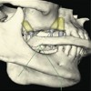
- 34. Restoration of Orbital Defects with Craniofacial ImplantsPrimary implant site v Supraorbital rim v Thick cortical bone v Periosteal blood supply
- 35. Orbital defects – Craniofacial implantsLateral portion of the supraorbital rim is preferred “ Better blood supply “ Presence of the frontal sinus
- 36. Orbital defects – Craniofacial implantsImplant sites are prepared in the usual fashion takinggreat care to avoid overheating the bone sites.
- 37. Orbital defects – Craniofacial implantsSecond stage surgery At second stage surgery care must be taken to carefully thin the tissues associated with the implant sitesTwo weeks after uncovering the Three week post second stageimplants surgery
- 38. Orbital defects – Craniofacial implants Magnetic retention is preferred “ Vision (depth perception) is impaired “ Ease of insertion and removalContours of the bar must fit within the confines of theprosthesis
- 39. Orbital defects – Craniofacial implantsMagnets are incorporated within ocular portion of the prosthesis Ocular portion fits within the confines of the silicone prosthesis. Bar secured Completed prosthesis
- 40. Orbital defects – Craniofacial implantsIn this patient implants were placed in supraorbital rimand the infra-orbital rim Magnetic retention used
- 41. Orbital defects – Craniofacial implantsEyeglass frames help to camouflage the prosthesis.
- 42. Maxillectomy-orbital exenteration defectIn this patient the orbital prosthesis was connectedto the completed denture obturator
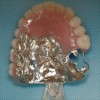
- 43. Maxillectomy-orbital exenteration defect v Obturator prosthesis and implant connecting bar completed v Note the magnetic attachments embedded within the obturator and the implant connecting bar. v An impression and cast are made as shown. v Magnetic attachments are positioned to limit the occlusal forces to the implants
- 44. Maxillectomy-orbital exenteration defecta b ec a: Tissue bar secured to master cast. b: Acrylic resin substructure. Magnetic attachments housed within substructure. c: Substructure seated. Ocular prosthesis secured to stone index.
- 45. Maxillectomy-orbital exenteration defect eSilicone casting. Note magnetic attachments. Theimplants are used to enhance the retention of the oraland facial prosthesis, but not to provide support for theoral prosthesis.
- 46. Maxillectomy-orbital exenteration defect v Implant connecting bar with magnetic attachments v Note perforation of inner canthus which provides aeration for skin around implants (arrow). v Completed prosthesis in position. It engages tissue bar and magnetic attachments associated with maxillary obturator (Courtesy Dr. Michael Hamada).
- 47. Supraorbital Rim Implants* (UCLA Data)N = 15 Success %Irradiated 4/19 21%Non-irradiated 12/28 43 %Totals 16/47 34% *Followup period 5 –13 years
- 48. Cranial Facial Implants Placed in the Orbital Rims to Retain Orbital Prostheses (UCLA Data) Soft Tissue Response Grade #Visits/Sites 0 14 1 15 2 9 3 5 4 7 Total 50
- 49. Orbital defects – Craniofacial implantsImplant failures: “ Poor hygieneAccumulation of keratin and sebaceous secretions lead toinflammation and bone loss around the implants
- 50. Orbital defects – Craniofacial implants Irradiated sites This patient received more than 6000 cGy to the implant sitesAnchorage is essentially mechanical as opposed to biologic.Flange exposure eventually led to inflammation and boneloss around the implants and eventually implant failure.
- 51. Connecting an orbital prosthesis to an obturator prosthesisFrequently, particularly with large defects, it is advantageous to connect a facialprosthesis to the oral portion in order to facilitate the retention of both prostheses.This practice is most effective when the oral portion is retained by implants orresidual dentition. We prefer to use magnetic attachments. These type ofattachments enhance the retention of both the oral and facial prosthesis but allowsome independent movement of each.
- 52. Connecting an orbital prosthesis to an obturator prosthesisOrbital prosthesis retained by magnetic attachment toRPD – obturator prosthesis.
- 53. Connecting an orbital prosthesis to an obturator prosthesis Orbital prosthesis retained by magnetic attachment to RPD – obturator prosthesis.
- 54. v Visit ffofr.org for hundreds of additional lectures on Complete Dentures, Implant Dentistry, Removable Partial Dentures, Esthetic Dentistry and Maxillofacial Prosthetics.v The lectures are free and available upon registering for the sitev Our objective is to create the best and most comprehensive online programs of instruction in Prosthodontics
New Lectures
 Restoration of Posterior Quadrants and Treatment Planning
John Beumer III DDS, MS
Robert Faulkner, DDS
Kumar C. Shah DDS, MS
Robert Faulkner, DDS
Kumar C. Shah DDS, MS
 Cement Retention vs Screw Retention
John Beumer III DDS, MS
Robert Faulkner DDS, MS
Robert Faulkner DDS, MS
 Angled Implants
John Beumer III DDS, MS
Allesandro Pozzi, DDS
Allesandro Pozzi, DDS
 Implants and RPDs
John Beumer III DDS, MS
Ting Ling Chang DDS
Robert Faulkner DDS
Ting Ling Chang DDS
Robert Faulkner DDS