Recent advances in implant surface sciences have dramatically improved the bio-reactivity of titanium implant surfaces. The new surfaces have accelerated the events associated with osseointegration and the bone deposited on the implant surface is harder and stiffer than the bone deposited on machine surface implants. In addition more of the implant surface becomes covered with bone. Several questions that are frequently posed by clinicians are “Do these new surfaces permit earlier loading? and “Do the new surfaces allow for more predictable immediate loading?” These two questions are addressed as well as other issues in this program of instruction.
Immediate and Early Loading — Course Transcript
- 1. 11. Early and Immediate Loading John Beumer III DDS, MS Distinguished Professor EmeritusDivision of Advanced Prosthodontics, Biomaterials and Hospital Dentistry, UCLAThis program of instruction is protected by copyright ©. No portion ofthis program of instruction may be reproduced, recorded or transferredby any means electronic, digital, photographic, mechanical etc., or byany information storage or retrieval system, without prior permission.
- 2. Three basic types of surfaces in use duringthe last 30 years. v Originalmachined surfaces v Micro-rough surfaces v Nano-enhanced surfacesv Do the new surfaces permit earlier loading?v Do the new surfaces allow for more predictable immediate loading?
- 3. Recent Advances in Implant Surface Science:Let us compare the science behind each of thesesurfaces from the perspective of early loading.v Original machined surfaces developed by Branemarkv Micro-rough surfacesv Nano-enhanced surfaces
- 4. Prerequisites for Achieving Osseointegrationv Uncontaminated implant surfacesv Creation of congruent, non-traumatized implant sitesv Primary implant stabilityv No relative movement of the implant during the healing phase
- 5. Prerequisites for Achieving Osseointegration Primary implant stability and no micro-movement during the initial phase of healing Submerged ImplantsMicro-movement disturbs the tissue and vascularstructures necessary for initial bone healing. v Davies (1994) found that excessive micromotion of the implant during healing prevents the fibrin clot from adhering to the implant surface. v Eventually, the mesenchymal stem cells migrating to the site are reprogrammed into fibroblasts leading to a connective tissue interface as opposed to a bone implant interface.
- 6. Prerequisites for Achieving Osseointegration Absence of micromotion during the healing period v Immediately following placement the bone contact area is approximately 10-15% even in favorable bone sites such as the anterior mandible. v If the implant is subjected to occlusal load at this point and mobilized, the mesencymal stem cells differentiate into fibroblasts and a fibrous connective tissue encapsulation results. With original machine surfaces it took 4 months to repair the trauma secondary to preparation of the implant site and develop sufficient bone anchorage to withstand occlusal loads
- 7. Early and Immediate Loading of Osseointegrated Implants v With the original machined surfaces, two stage surgical procedures were employed, primarily to reduce the risk of micro-movement during healing v In the mandible the implants were allowed to rest beneath the mucosa for 3 months before uncovering, in the maxilla for 6 months v When machine surface implants were placed into function immediately following surgical placement, the failure rates were about 20% v Have the micro-rough and now the new nano-enhnanced surfaces allowed clinicians to place these implants into function earlier or immediately with better predictability?To answer this question we need to understand the reasons why these newsurfaces represent an improvement over the original machined surfaces.
- 8. Titanium Implants – 2nd Generation Why are they an improvement?Definition: Micro-rough surfaces –Peaks and valleys are one mm apart. This surface roughness can be created by: ” Electrolytically ” Acid etching the surface ” Combination acid etching and sand blasting ” Titanium dioxide grit blasting 1 micron
- 9. Micro-rough Surfaces Micro-rough surface textures – Why are they a significant improvement ” Improved adsorption of plasma proteins ” Better retention of the fibrin clot ” Cell adhesion enhanced ” Cell differentiation accelerated ” Cell activity – Gene expression upregulated and accelerated” Shape of the cell affects its gene expression.” The microenviroment affects cell behavior.
- 10. Micro-rough Surfaces Micro-rough surface textures – Why are they a significant improvement ” Improved adsorption of plasma proteins ” Better retention of the fibrin clot ” Cell adhesion enhanced ” Cell differentiation accelerated ” Cell activity – Gene expression upregulated and acceleratedResult: ” More bone contact area on the implant surface
- 11. Micro-rough surfaces Why are they a significant improvementv Kohavi (2010) – Initial adsorption of plasma proteins isenhanced by the microrough surfacesv Davies (1998) showed that micro-roughsurfaces captured and retained the fibrin clotinitially deposited on the implant surface moreeffectively than machined surfaces and therebybetter facilitated the initial events (clotformation, angiogenesis, osteoprogenitor cellmigration etc.) associated with osseointegration.v Ogawa and Nishimura (2000, 2003 and 2004)showed that micro-rough surfaces changes geneexpression of the differentiating osteoblasts
- 12. 50 µm HistomorphometryAcid etched vs Machine surface Near zone Far zone Machined Acid etched (%) 80 * 60 40 * The events associated 20 with osseointegration are 0 W2 W4 also accelerated as indicated in the chart. Bone-implant contact ratio (Ogawa and Nishimura, 2000, 2003),
- 13. 50 µm HistomorphometryAcid etched vs Machine surface Near zone Far zone Machined Acid etched (%) 80 * 60 40 * 20 Why is the process accelerated? 0 W2 W4 Bone-implant contact ratio (Ogawa and Nishimura, 2000, 2003),
- 14. Gene Expression Machine Surface vs Acid Etched SurfaceT-cell implant Machined Acid-etched ” Ogawa and Nishimura implanted T-cell shaped implants into the femurs of rats and retrieved the specimens at various time intervals. ” They hypothesized that gene expression is controlled at local levels by the surface texture of the implant.
- 15. Pattern A Implant-free osteotomy Machined implant D3 W1 W2 W4 D3 W1 W2 W4 DAE implant Col I OPN Pattern B Osteopontin upregulated Osteocalcin upregulated (Calcium binding molecules) D3 W1 W2 W4 D3 W1 W2 W4 ONC OCN Pattern C D3 W1 W2 W4 D3 W1 W2 W4 D3 W1 W2 W4 D3 W1 W2 W4 BSP II Col III IGN b-1 IGN b-3 They found that osteopontin and osteocalcin, genes associated with thecalcification process were upregulated and their expression accelerated by themicro-rough surface.
- 16. Pattern A Implant-free osteotomy Machined implant D3 W1 W2 W4 D3 W1 W2 W4 DAE implant Col I OPN Pattern B Osteopontin upregulated Osteocalcin upregulated (Calcium binding molecules) D3 W1 W2 W4 D3 W1 W2 W4 ONC OCN Pattern C D3 W1 W2 W4 D3 W1 W2 W4 D3 W1 W2 W4 D3 W1 W2 W4 BSP II Col III IGN b-1 IGN b-3 They also noted that the bone applied to the micro-rough implant surfaces appearedto be different than the bone deposited on the machined implant surfaces.
- 17. Why was the bone different?Nishimura and Ogawa suggestedseveral reasons including: Bone repair and generation may not be the primary prerequisite for osseointegration” Might it be an implant dependent mechanism?” Hypothesis: ! A set of genes that are NOT involved in bone repair initiate and/or regulate the process of osseointegration Ogawa and Nishimura, 2000, 2002, and 2003!
- 18. Purpose of the studyIdentify the genes that are expressed around implantsbut not in non-implant wound healing of bone.” Non-implant defect Turned implant Etched implant Screening of candidate osseointegration-specific genes Differential display polymerase chain reaction (DD-PCR)
- 19. Testing the candidate DD-PCR products” From 1853 DD-PCR products, 19 implant-specific (- + +) 2 acid-etched-specific (- – +) 42 different clones 3 Osseointegration-specific genes (TO1, TO2 and TO3)These genes were expressed only in the bone formedaround a titanium implant and were not expressed innormal healing bone absent the implant
- 20. TO genes showedOsseointegration-specific expressionUpregulation in early stages of implantationAccelerated expression for the double acid etched surface
- 21. TO3 happens to be P4HEnhanced gene expression of prolyl 4-hydroxylase (P4H) ” This gene is associated with collagen synthesis
- 22. Collagen and P4HP4H
- 23. Why was the accelerated expression of P4H on micro- rough surfaces significant?” Collagen density and orientation, as well as the degree of mineralization are contributing factors relative to the microhardness and elastic modulus of bone
- 24. Bone Implant Interface Double Acid Etched Surfaces” Collagen synthesis is initiated earlier by the osteoblasts adhering to the micro-rough implant surface” A different combination of collagenous and noncollagenous proteins make up the bone deposited on the dual acid etched surface as compared to a machined surface.” As a result resorption and remodeling of bone deposited on acid etched surfaces appears to be different than bone deposited on
- 25. Distinct osteogenesis on DAE Day 14 7 Day 21 0 28 3 Osteoblast Non-collagenous matrix Mineral deposition Collagen matrix
- 26. Nano Scratch Test 3 times harder bone on dual acid etched 2000nm indentation depth P=0.0252 Nanohardness P=0.0339 (GPa) 0.2 0.1 0 Bone on Bone on Bone on Polystyrene Machined Ti DAE
- 27. Nano indentation test 2 times harder bone on dual acid etched 200mN maximum load P=.0005 P=0.0153 P=0.0130 Nanohardness 0.8 (GPa) 0.6 0.4 0.2 0 Bone on Bone on Bone on Polystyrene Machined Ti DAE
- 28. Nanoindentation: in vivo boneOgawa et al, 2005Bone deposited on machined surfaces is equivalent inhardness to trabecular bone, while the bone around theDAE surfaces is as hard and stiff as the cortical bone. “
- 29. Impact of Strengthened Peri-implant Bone Trabecular bone Cortical boneCortical bone: l Very dense l Less subject to resorption or remodeling
- 30. Micro-rough surfaces Surface roughness and the bone contact areaAnimal studies have shown that the bone contact areaachieved is 50% greater with micro -rough surfaces ascompared to machined surfaces (Buser et al, 1991, Weinlander,1993, Hamada, 1995, Nishimura and Ogawa, 2000, 2003).There appears to be little difference in bone contact areaachieved after implant placement between the mostcommon microrough surfaces currently on the market.. Courtesy Dr. M Weinlander
- 31. Bone contact area Microrough surfaces (Weinlander et al, 2004)70 64.15 65.03 61.6960 51.53 48.150 44.7 37.740 34.8 1. 2X30 2. 10X20100 NBC- TiU 3I ITI Xive- CP Courtesy Dr. M Weinlander
- 32. Enhancement of titanium surfacesFluoride treated surfaces (Astra) v Improves the wetability of the surface v Cbfa expression is high for the grit blasted fluoride prepared surface (Isa et al, 2006) ” Cbfa is a transcription protein that promotes cell differentiation of osteoprogenitor cells) ” Accelerates the events leading to deposition of bone on the implant surface
- 33. Enhancement of current titanium surfacesSLA active (implant packaged in saline) (Strauman) ” Maintains the wetability of the surface ” Wetable surfaces significantly enhance initial adsorption of plasma proteins ” This, in turn facilitates migration, adhesion and differentiation of mesenchymal stem cells
- 34. Titanium Implant Surfaces” 1st generation! 2nd generation! 3rd generation Machined surface” Nano-enhanced” Ti blasted surface! Sand-blasted surface” surfaces NO DIFFERENCE! • HA crystal TPS” Sand-blasted, ! deposition HA coated surface” acid-etched • Titanium particle surface! Genetically Dual acid-etched ! engineered surface! Electrolytically Recombinant enhanced! proteins-BMP
- 35. Nano-enhancement of implant surfaces Potential Benefitsv Increased surface area and with it better interlocking of the bone to the implant surfacev Enhanced wetability and adsorption of plasma proteinsv More favorable surface chemistry with HA- CaP coatings and TiO2 pico-nanometer coatings
- 36. Effect of Nano-Structure:Long-term stability of osseointegration v Recent theoretical models suggests there is increased mechanical interlocking of bone with nano-structured surfaces. Loberg et al, Open Biomater J, 2010 Hansson et al, Open Biomater J, 2010
- 37. Effect of Nano-Structure: Cell response Overwhelming numbers of studies report significant effect of nano-structure on cellular behaviorsHuman corneal epithelial cells with Fibroblast growth was inhibited 70nm groove (A) or flat surface (B) on nano-‐structured surface
- 38. proportional to the protein binding affinity [33,44]. fluorescent signalapproach, commercial micp with a fluorescence PSIM results show that surface nanoscale morphology 2A). For investigating the role of nanoscal (Fig. drasti- FPQ consists in imaging t Effect of Nano-Structure: cally influences the amount of adsorbed proteins. Theprotein adsorptionperpendicular a PSIM exper saturation we performed to the surfac uptake significantly increases as nanoscale roughnessdifferent concentrations of bovine serum albumi increases. immediately after photoble gen and streptavidin (10 replicates per concent Surprisingly, when changing surface roughness by 15 nm,nanostructured surfaces described above titania the zone allows accurate m Controlled protein adsorption saturation uptake increases up to 600%, depending on mentary Discussion S1 for proteins charact Figure 1. Nanostructured surface synthesis. (A–C)also images of the protein background fluorescence, used (Fig. 3A, 3B, 3C). Results AFM demonstrate that thewe studied 1,200The background surface morphology for sample 1 (SMP1, A), sample 3 (SMP3, B) and experiment solution. protein-surface int adsorption mechanism follows different modalities than those sample 5 (SMP5, C). Colour scale range is 0–120 nm (black to white). (D) ing protein adsorption isotherms on aberra affected by optical nanostr expected, since the effect produced by increasing roughness 2C,not 2E). The Langmuirisisotherm m Schematic view of the supersonic cluster beam deposition (SCBD) (Fig. is 2D, adsorbed layer isolated justified doi:10.1371/journal.pone.0011862.g001 v Protein adsorption apparatus equippedby mere geometry, i.e.cluster creation of new widely used protein adsorption model [44], adequ with a pulsed microplasma the source (PMCS). adsorption from the raw signal. Addi our experimental data for all the tested proteins ( sites. If this were the case, the amount of adsorbed proteins should increased significantly increase linearly at most, as a function of the sample specific area, proteins in the solution i quantify the layer signal (Fi because www.plosone.org on ~30nm structured PLoS ONE | of the consequent increase of adsorption sites. Moreover, since samples have identical surface chemistry, binding affinity 2 July 2010 | Volume 5 | is worth stressing that FP principle, may be applied TiOx surface. would be expected to remain constant when nanoscale morphol- rough surface. Fig. 4A and ogy changes. However, measured SU is not directly proportional adsorbed on samples 1 a to the number of adsorption sites on the surface; in fact, the surfaces in the previous normalized saturation uptake (NSU), defined as the SU divided by detected the same non-line v Surface nano-structure the sample specific area, follows an evident growing trend for all we observed with PSIM, w the considered proteins (Fig. 3A, 3B, 3C). This shows that the of adsorbed proteins on s determines the protein increase in protein adsorption is more than linear as a function of (Fig. 4A, 4B). Quantitati adsorption the increase of disposable adsorption space on the surface. calibration and the mea PLoS ONE | www.plosone.org 3 JScopelliG et al, The effect of surface nanometre-‐scale morphology on protein adsorpGon, PlosOne, 2010
- 39. Effect of Nano-Structure: Controlled protein adsorption v Protein adsorption to nano-structured surfaces requires less energy than to a flat surface v Nano-structure orients the direction of adsorbed proteinSabirianov et al, Enhanced iniGal protein adsorpGon on engineered nanostructured cubic zirconia
- 40. Nano-coating of HA-CaP Crystalsapplied to the miro-rough surfaces
- 41. Nano-coating of HA-CaP Crystalsapplied to the miro-rough surfaces
- 42. Shear Strength (MPa) – DAE Ti-nanoHA Chemical Bonding? Machined Ti DAE Ti DAE Ti-nanoHA Shear Strength Shear strength at 2 wk 12 11 10 S=F/A [N/mm2] Shear Strength [MPa] 9 8 7 6 5 4 3 2 1 – 2
- 43. A B Synergistic effect of DAE topography 0 7mm 11mm 15mm and HA nano-layer: Over 100% increase in the bone-implant anchorage C D 25 30 Nishimura and 20 Butz et al, 2004 25 o ad (N) 15 10 5 20 L 0 Machined 15 0 0.1 0.2 0.3 Acid etch Displacement (mm) Acid etch HA E 10 140 (%) n test value 120 5 N or maliz ed 100 0When nano-HA coating was added to conventional smooth and DAE implants, pus h- i 80bone anchorage was increased over 100%. In fact DAE Ti-nanoHA implant 60showed theof implant12(degree) Inclination accelerated bone-implant integration at the level that has never 0 4 8 16been reported.
- 44. Bone-implant integration Machined DAE+HA-nano-topography boneWeak Link – Cement Line” Smooth implant was almost naked because surrounding bone did not stayon implant.” DAE plus nano-HA was covered by the surrounding bone indicating thatbonding was so strong the push-in force fractured the bone.
- 45. Bone-implant integration Machined DAE+HA-nano-topography boneThe bond between the bone and implant surface was greaterthan between the new bone and old bone.No cement line?
- 46. Titanium Implants – Surface ModificationsNano-surface modification with titanium particles Further enhancement of the surface topography Increased surface area l Almost 100 % of the surface of the implant is covered with bone
- 47. Pico-super-thin surface modification of Tiv Ogawa and associates have shown that a pico- meter thin TiO2 coating improves the bioreactivity of microrough implant surfaces by modulating its surface chemistry while preserving the existing surface morphology Sugita et al, 2011
- 48. No surface thin as 300 pm change before and after As topography The coating is as thin as 300 pmControl Ti! Liquid TiO2 – 15 min!The micro-rough topgraphy is unchanged by the coating Sugita et al, 2011
- 49. Effects of pico-nanometer TiO2 CoatingImpact on osteoblasts v Improves cell attachment v Enhances spreading behavior v Increased proliferation v Accelerates differentiation
- 50. Increased osteoblast proliferation (Day 2) P<0.05 BrdU incorporation / cell 0.3 0.2 0.1 0 Untreated Liquid TiO2 coated N=3 Sugita et al, 2011
- 51. Rate of Osteoblastic Differentiation Enhanced bone cell function (Day 5) P<0.05ALP activity 0.15 0.1 0.05 0 Untreated Liquid TiO2 coated N=3 Sugita et al, 2011
- 52. Bone-related gene expression (Days 7 and 14) Sugita et al, 2011
- 53. Mineral deposition (Day 14) Sugita et al, 2011
- 54. Control! Liquid TiO2 coated!Mineralized nodule area at day 14 (arizarin red) Control! Liquid TiO2 coated! Sugita et al, 2011
- 55. Clinical Impact of advances in implant surface science?” The biologic events leading to osseointegration have been accelerated ” Cell differentiation, adhesion and gene expression is enhanced” Better bone anchorage ” The bone deposited on the micro-rough surfaces is denser and stiffer Does this make a difference regarding early loading or the predictability of immediate loading?
- 56. Clinical Issues” Earlier loading. ” Yes!!” Immediate loading. ” Probably not!!
- 57. Do these data justify the concept of Earlier Loading?Yes!! Several animal and human studiesindicate that under the right conditions,earlier loading of osseointegrated implantsis possible. l Micro-rough Surfaces l 6-8 weeks l Nano-enhanced surfaces l 2-4 weeks?
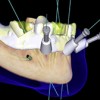
- 58. Immediate Loading? Probably not!!! 3D Simulation software and CAD CAM technologiesenables the fabrication of the prosthesis before implantplacement ” With the new 3D simulation software now available it is now possible to fabricate various types of prostheses (primarily provisional) prior to surgical implant placement. Courtesy T. Sugai
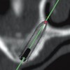
- 59. 3D Simulation SoftwareThe implant lengths, type, angulation and position can be determinedand a surgical drill guide can be designed and fabricated with CAD-CAM technologies. Courtesy Dr. T. Sugai
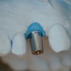
- 60. 3D Simulation Software CAD/CAM The data isdeveloped andinputted and thesurgical drillguide is milled. Courtesy T. Sugai
- 61. Immediate LoadingThe implants are placed, torqued to the prescribed amount andthe premade provisional prosthesis is secured. Courtesy T. SugaiResonance frequency analysis
- 62. Immediate loading?” Do these data make immediate loading more predictable. No they do not!!!” Immediate loadingis still a dependent upon the quality of initial anchorage Success is dependent upon the absence of micro motion of the implant during the healing period.
- 63. Micromotion Two types of micromotion: it may be tolerated , or it may be deleterious Micromotion of less than 100 micros appears to permit bone ingrowth, Macromotion appears to preclude it 50µm 100µm 500µm Tolerated DeleteriousFrom Maniatopoulos et al, J Biomed.Mater Res 1986Szmuckler and Monclear, Clin Oral Implant Res, 2000
- 64. Immediate Loadingv For the implant to become osseointegrated it must remain immobilized during the healing period.v Thereforethe key to successful immediate loading continues to be the effectiveness of primary implant stability
- 65. Initial Primary Stability (First day)Function of: Courtesy Dr. C. Stanford v Localbone quantity and quality v Implant geometry ” Tapered better than cylindrical because you have a better chance of maximizing bone contact with the internal and external diameters of the implant v Surgical procedure (skill) ” Insertion torque – in excess of 45 NewtonsTwo main factors: 1. Amount of initial bone contact 2. Lateral compression of the osteotomy site creating local compression stresses (hoop stresses)
- 66. Will these stresses lead to pressure necrosis of the investing bone? Courtesy Dr. C. Stanfordv Branemark maintained that necrosis of bone occurred if implants were initially anchored at torques about 45 Newtons an impaired the process of osseointegration Is this true?v There is no evidence to substantiate this claim.v Indeed, higher insertion torques may actually lead to better bone anchorage (Trisi et al, 2011). Be careful with regard to implant selection. Some implants may fracture or the hex may be stripped at higher levels of torque during insertion.
- 67. Immediate Loading – When Is it Feasible? Clinical issues to be considered:The degree of initial bone anchorage v Skill of the surgeon. Immediate loading is not for beginners ” Consider bicortical stabilization when possible ” You must attempt to engage the inner and outer diameter of the implant with bone when appropriate ” Insertion torque – in excess of 45 Newtons ” ISQ’s – 70 and above v Volumeand density of the bone associated with implant site ” Sites with dense trabecular bone are preferred ” Longer implants are generally preferred
- 68. Immediate Loading – When Is it Feasible? Clinical issues to be considered: Tapered vs CylindricalImplant geometry v Tapered better than cylindrical because you have a better chance of maximizing bone contact with the internal and external diameters of the implant upon initial insertion.
- 69. Immediate Loading – When Is it Feasible? Clinical issues to be considered: Implant geometry v Avoid implants with voids associated with the apical portion particularly in extraction sites v In extraction sites most of the anchorage is in the apical third of the implant
- 70. Immediate Loading – Clinical issuesOcclusal loads, occlusion and provisionals” Control the occlusion. Most damage is done by “para-function “ ” Bilateral balance for patients with at least one edentulous arch ” Clinical remounts are essential ” Anterior guidance for posterior quadrant cases ” Anterior single teeth out of occlusion
- 71. Immediate Loading Clinical issues to be considered:Compliance v Post op instructions must be clear ” Patient must avoid tough foods during the first month after implant surgery ” Taking the prosthesis out of occlusion may not be sufficient. Remember, teeth do not come into contact during mastication of the bolus. ” Implants are most vulnerable to mobilization and loss during the 1-3 week transitional period between implant placement and when a reasonable bone implant contact area is achieved v Contra-indicated in those with chronic bruxism
- 72. Immediate Loading – When Is it Feasible? Clinical issues to be considered: ” Cost ” Clinician and patient must be willing to accept a 5-20% lower success rate
- 73. The Keys to Immediate Loading:v Initial immobilization of the implant v Maximize implant lengthv Maintaining anchorage during the dip in anchorage during the transitional period between implant placement and when there is a reasonable level of bone deposition. v During this one to three week period, the implants are most vulnerable to micro-movement and failurev Occlusion v Clinical remounts necessary to refine the occlusionv Patients with significant para-functional habits are poor candidates for immediate loading
- 74. Fixed in Edentulous Mandiblev This patient is a good candidate for immediate loading.v Favorable bone sitesv Minimal defects secondary to extraction. Note the super eruption of the teeth and alveolus associated with the incisors. Therefore alveolectomy is performed to create sufficient interocclusal space for the proposed prosthesis anteriorly.
- 75. Fixed in Edentulous MandibleGood initial anchorage v Insertion torque of in excess of 45 Newtons v ISQ values of 70 and above v Maximize implant lengths
- 76. Fixed in Edentulous patientsv Additional implants are usually employed in an immediate loading case v Note that in this patient 6 have been placed as opposed to the usual 4 or 5 implants
- 77. Fixed in Edentulous Mandiblev Limit cantileversv Rigid frameworks enhances cross arch stabilizationv Clinical remount record to refine the occlusion (bilateral balance,group function, etc depending upon the status of the opposing arch)
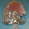
- 78. Fixed in Edentulous Maxillav Good initial anchorage v Insertion torque of in excess of 45 Newtons v ISQ values of 70 and abovev Rigid frameworks v Limit cantilever length. Note that there are no cantilevers in this prosthesis
- 79. Fixed in Edentulous Maxillav Rigid frameworks to enhancecross arch stabilizationv Place additional implantswhen possiblev Maximize implant lengthv Clinical remount record torefine the occlusion
- 80. Edentulous Mandible Immediate loading of Implant assisted overdentures in the mandible “O” ring attachmentv Immediateloading with overlay dentures using “O” rings forretention may not be as predictable as first thought. In a recentstudy (Kronstrom et al, 2010) the loss rates approached 20% at12 months.v Therefore, we would not recommend this option.
- 81. Immediate Loading Single tooth defects v Predictable in experienced hands in the incisor region v Not recommended in the cuspid region because of the difficulty in controlling lateral forces in this area
- 82. Immediate Loading Posterior quadrantsLinear configuration – Posterior quadrantsNot recommended
- 83. v Visitffofr.org for hundreds of additional lectures on Complete Dentures, Implant Dentistry, Removable Partial Dentures, Esthetic Dentistry and Maxillofacial Prosthetics.v The lectures are free.v Our objective is to create the best and most comprehensive online programs of instruction in Prosthodontics
New Lectures
 Implants and RPDs
John Beumer III DDS, MS
Ting Ling Chang DDS
Robert Faulkner DDS
Ting Ling Chang DDS
Robert Faulkner DDS
 Computer Guided Treatment Planning and Surgery
John Beumer III DDS, MS
Allesandro Pozzi, DDS
Robert Faulkner DDS
Allesandro Pozzi, DDS
Robert Faulkner DDS
 Cement Retention vs Screw Retention
John Beumer III DDS, MS
Robert Faulkner DDS, MS
Robert Faulkner DDS, MS
 Prosthodontic Procedures and Complications
John Beumer III DDS, MS
Robert Faulkner, DDS
Robert Faulkner, DDS