Transcript of ” Prosthodontics Procedures and Complications – Posterior Quadrants”
1. Prosthodontic procedures and complications – Posterior quadrants John Beumer III DDS, MS Robert Faulkner DDS Division of Advanced Prosthodontics, UCLA This program of instruction is protected by copyright ©. No portion of this program of instruction may be reproduced, recorded or transferred by any means electronic, digital, photographic, mechanical etc., or by any information storage or retrieval system, without prior permission.
2. Exam and workup l Chief complaint l History of the present illness l Medical and dental history
3. Exam and workup l Missing teeth l Occlusal plane l Loss of OVD l Occlusal scheme
4. Exam and workup l Don’t forget that conventional prosthodontic methods can be use address many of these deficiencies
5. Selection of implants l Surfaces l Geometric designs
6. Selection of implants l External hex vs. internal connection l Platform reduction l Geometric design of the neck l Location of the implant/abutment connection l Stability of the implant/abutment connection l One piece designs l Co-axis designs
7. Selection of implants Design of the implant body l Internal connections are more stable as compared to external hex l Preferred in single tooth restorations l This issue is probably not clinically significant when splinting non engaging multiple units together l Tapered implants achieve better primary stability l Preferred for immediate loading
8. Platform Switching (Reduction) Will this type of implant fixture – abutment configuration minimize the bone loss around the neck of implants? v Based on a review by Bateli and Strub (2011) “the current literature provides insufficient evidence about the effectiveness of any specific modification in the implant neck area in preserving marginal bone or preventing marginal bone loss”
9. Platform reduction l Recently conducted radomized clinical trials indicate no advantage in terms of maintaining marginal bone levels (Annibali et al 2012; Enkling et al, 2013)
10. Geometric design of the neck l Positive slope vs negative slope l Presence of micro-threads l Evidence indicates there is no difference in marginal bone loss
11. Location of the implant/abutment connection l Subcrestal vs supracrestal l Evidence indicates there is no difference in marginal bone loss
12. Stability Implant/abutment connection l Multiple tooth restorations vs single tooth restoration. l Size of the micro-gap l Bacterial colonization of the micro-gap
13. Marginal Bone Loss Based on a Med Line search, a review of the literature indicated that no implant system, surface or design was found superior with regards to marginal bone loss (Abrahamsson and Berhlundh, 2009)
14. One piece designs Advantages No implant abutment connection Problems l Cement retained l Require intra-oral preparations l Time consuming l Difficult l Misaligned implants l Difficulty in obtaining proper retention form and resistance form
15. One piece systems Nobel direct and similar one piece systems There are no gaps developing between an abutment and fixture. Why the bone loss? Most have modern surfaces. Many were immediately provisionalized and loaded with cement retained restorations. In many cases the cement extended down to the boney levels v An inflammatory response was initiated which was progressive and irreversible leading to extensive bone loss.
16. Co-axis designs l Desiged to account for the anatomy of the alveolar ridge l Permits subgingival angulation correction l Issues l Biomehanics l Surgical placement difficult
17. Selection of implants l The best implant anchorage is achieved with implants prepared with micro-rough surfaces and they are dramatically superior to machine type surfaces. l There appears to be no significant advantage of platform reduction with respect to maintenance of marginal bone or the long term survival of implants.
18. Selection of implants l On the basis of theoretical and laboratory studies, internal connections are more stable and demonstrate smaller micro-gaps when exposed to off angle loads. l Since these studies were based upon single tooth applications, it is unclear whether there are clinically significant differences between these two implant/abutment connection designs with regards to splinted multi-implant prostheses. l Based on animal studies, implant/abutment connections that are sub-crestal lead to more marginal bone loss than connections that are equi-crestal or supra-crestal. However, the evidence based on human studies is indeterminate.
19. Selection of implants l Properly designed, randomized clinical outcome studies are not available assessing whether internal connection implant/abutment interfaces are superior to external hex designs when restoring posterior quadrants with implant supported fixed partial dentures.
20. Implant site evaluation and selection Conventional methods l Diagnostic wax-up l Fabrication of a radiographic guide
21. Implant site evaluation and selection Conventional methods l Radiographic guide
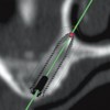
22. l The middle implant is tilted distally and medially in order to maximize length and to enable anchoring the tip of the implant in cortical bone CAD-CAM
23. CAD-CAM l Scan the wax-up and proceed
24. CAD-CAM l Fabricate a model l From the model, make a surgical drill guide (template)
25. CAD-CAM l Forego the 3D model l Identify implant positions
26. CAD-CAM l Change lengths, diameters, angulations etc. via the internet with 3 – way consultation between the surgeon, prosthodontist and the milling center.
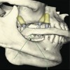
27. CAD-CAM l The implant sites, implant lengths and diameter have been chosen. l A surgical drill guide (template) can be milled or made with a 3D printer Inferior alveolar nerve
28. CAD-CAM l The surgical drill guide permits fully guided implant placement
29. CAD-CAM l Such practice ensures that the implants will be in the proper position and alignment and the desired apical-coronal depth
30. CAD-CAM l These programs can also be used to design and mill custom abutments
31. CAD-CAM l The definitive restorations. It has been cemented. Note the supragingival margins.
32. l These custom abutments were designed before placement of the implants CAD-CAM Courtesy Dr. A. Pozzi
33. l Definitive prosthesis CAD-CAM
34. Abutment selection v Prefabricated (stock) v Cement retained v One piece v Two piece v Angled v Screw retained v Angled abutments v Prepable abutments v UCLA abutment v Custom abutments v Conventional methods v CAD-CAM designed and milled
35. Abutment selection Cement vs screw retention Screw retained restorations l Advantages l Retrievability – important if laminated porcelain is used to restore the occlusal surfaces and repair or recontouring of the prosthesis is needed l When limited interocclusal space does not permit the development of axial walls of sufficient thickness for proper retention and resistance form l Disadvantages l Screw access hole on the occlusal surfaces is unesthetic and may compromise the position of occlusal contacts l Abutment screw retention requires perfect alignment and angulation of implants l Cross linking screw retention requires skilled lab support and is costly
36. Abutment selection Cement vs screw retention Cement retained restorations l Advantages l Simplicity – It’s a common procedure in the dental office l Angulation problems are easier overcome l No screw access hole on the occlusal surfaces l Better esthetics l More control of occlusal contacts l Disadvantages l The margin is not scalloped to follow the gingival margin making it difficult to remove subgingival cement l Subgingival cement retention – peri-implantitis can lead to loss of the implants and adjacent teeth l Most dentists are not familiar with the techniques used to cement an implant retained prosthesis l If the abutment screw becomes loose, the restoration will probably be destroyed while gaining access to the screw
37. Abutment selection Prefabricated vs custom abutments Cemented restorations Custom abutments are preferred because: l Better control the thickness of metal and porcelain making chipping and fracture of the occlusal surfaces less likely l Control the margin of the restoration in relation to the gingival margins making it easier to retrieve cement
38. v Carry restoration more subgingivally than we can predictably remove cement. v For more ideal emergence profile and contour. v Avoid trapping cement subgingivally v More predictable seating of bridge or pontic v Better retention particularly when a cemented restoration would have a very short axial wall. v Easier to restore when there is limited inter- occlusal or restorative space Arguments in favor of screw retained restorations
39. Abutment selection Prefabricated vs. custom abutments Cement retained implant crowns with laminated porcelain occlusal surfaces When a metal ceramic crown is fabricated to engage a stock abutment, often the metal core is uneven and excessively thick. Residual stress can build up during addition of the porcelain predisposing to chipping and fracture of the prosthesis.
40. Abutment selection Prefabricated vs. custom abutments l The position of the margin can be controlled with custom abutments. It is difficult to remove cement when it becomes impacted subgingivally. Prefabricated abutments Prefabricated abutments Custom abutments
41. Abutment selection Prefabricated (stock) l Cement type One piece system Problem – Cement margin is often several mm subgingival making removal of cement problematic Two piece system
42. Abutment selection Prefabricated – Screw retained Issues and concerns l Loosening and fracture of prosthetic screws
43. Abutment selection Prefabricated – Screw retained Angled abutments Issues and concerns l Biomechanics l Emergence profile l Esthetics
44. Abutment selection UCLA abutment l The restoration directly engages the head of the implant fixture without an intervening abutment
45. Abutment selection UCLA abutment Advantages l No cement margin l Porcelain extended subgingivally l Can be used when there is minimal interocclusal space l Account for poor angulation Disadvantages l Abutment screw access hole on the occlusal surface
46. Abutment selection UCLA abutment Can be used to make custom abutment for either a cement retained or screw retained (cross pinning screws) prosthesis 1. Used to overcome misaligned implants 2. Used when a porcelain occlusal surface is desired
47. Abutment selection Prepable abutments Issues l Misangled implants l Time
48. Custom abutments Two methods of fabrication Conventional CAD-CAM l Account for difficulties in alignment, position and angulation l Better control of occlusal factors such as width of the occlusal table l Permits the use of a cemented restoration with complete control of margin placement
49. Custom abutments Conventional methods l These custom abutments were designed to retain the prosthesis with cross pinning screws
50. Custom abutments CAD – CAM method l These abutments were milled from titanium, nitrite coated. They are designed to retain the prosthesis with cement
51. Custom abutments CAD – CAM method Design criteria l Anatomic form/contour abutment l They are designed according to the emergence profiles of teeth being replaced and often blanch the tissue when seated. They are generally not used in the esthetic zone.
52. Custom abutments CAD – CAM method Design criteria l Support contoured l Abutment designed to support the soft tissue contoured with a provisional restoration.
53. Custom abutments CAD – CAM method Design criteria l No tissue displacement l These abutments are slightly under contoured, and are often used when a stock healing abutments have been employed.
54. Custom abutments CAD – CAM method Design criteria l The abutment design on the right is of concern because of subgingival cement accumulations may be difficult to access and remove Anatomic form/contour No tissue displacement Support contoured soft tissue
55. Custom abutments CAD – CAM method Materialsl Titanium l Zirconia l Chrome – cobalt Zirconia is not recommended in the posterior quadrants because of the risk of fracture (Canullo et al, 2013; Sghaireen, 2013)
56. ❖ The treatment procedure is similar to current methods Shape memory sleeve abutment system
57. ” ‣ Nitinol is safe and bio-compatible ‣ Many devices are approved by FDA ‣ Economical to manufacture Arch bars Heart balloon Heart stent (Nickel titanium alloy) Shape memory sleeve abutment system
58. Shape memory sleeve abutment system l The flaps of the sleeve engage the abutment and the out flaps engage coping of the implant crown
59. Shape memory sleeve abutment system
60. Shape memory sleeve abutment system l The crown can be removed by transmitting an electric current through the coping and into the shape memory sleeve
61. Provisional restorations l Used to resolve issues regarding esthetics, occlusal scheme, and prosthetic design. l The posterior teeth on both sides of the arch are restored with implans
62. Provisional restorations milled from PMMA and designed with CAD programs Provisional can be designed and milled with CAD-CAM programs. This prototype was milled from a block of PMMA. Courtesy Dr. M. Moscovitch
63. Impressions l Transfer copings with closed tray for linear configurations Fabricating the definitive restorations
64. Fabricating the definitive restorations l Make records and mount casts l Transfer records to the articulator
65. Fabricating the definitive restorations Virtual articulation and design programs
66. Fabricating the definitive restorations – Occlusal factors l Narrow the occlusal table l Buccalize or lingualize as required l Centric only contacts
67. Fabricating the definitive restorations – Hygiene access l Smooth emergence profiles l Proxy brush access
68. Fabricating the definitive restorations – Pontic design l No ridge laps l Modified ridge lap pontic designs are favored in the posterior quadrants
69. Fabricating the definitive restorations Custom abutment designs – Cement retained l Avoid abrupt changes in contour at the margin of the restoration l Place margins slightly supra- gingival
70. Fabricating the definitive restorations – Occlusal materials l Occlusal forces delivered into the bone anchoring the implants are not effected by the nature of the occlusal material (Gracis et al, 1991) Metal Laminated porcelain Monolithic zirconia
71. Fabricating the definitive restorations – Occlusal materials Metal Laminated porcelain Monolithic zirconia Criteria for selection based upon: Wear characteristics Nature of the dentition in the opposing arch Potential for failure Esthetics Parafunctional activity
72. l Preferred Fabricating the definitive restorations – Occlusal materials
73. Fabricating the definitive restorations – Occlusal materials Laminated Porcelain Issues l Fracture and chip rate has been reported as high as 22% when the framework is made of zirconia (Nothdurft et al, 2013)
74. Fabricating the definitive restorations – Occlusal materials Monolithic zirconia l PMMA prototype adjusted l Scanned l Fabricated in zirconia l Initial data is promising but short term (Moscovitch, 2015) Courtesy Dr. M. Moscovitch
75. Fabricating the definitive restorations – Try in l A jig designed to correctly orient multiple abutments made of metal
76. Fabricating the definitive restorations – Try in l A jig designed to correctly orient multiple abutments made of pattern resin
77. Fabricating the definitive restorations – Delivery l Occlusal adjustment l Two thicknesses of mylar should pass through the implant contact when the natural teeth hold one thickness l Proximal adjustments l Two thicknesses of mylar
78. Note: The cusp angles are flat and the occlusal tables are narrow Result: Lateral forces on the implants are minimized Anterior group function with centric only contact
79. Group function Patient in right working position. Note lateral guidance is provided by the premolars and the central incisor. Result: Lateral forces on the implants are minimized. Courtesy Dr. M. Hamada
80. Anterior (canine) Guidance Space allowed only two implants to be placed in this patient. However, note anterior guidance. Design the occlusion to minimize the delivery of nonaxial forces Courtesy Dr. M. Hamada
81. Group function • Only two implants have been placed to restore the corner of the arch in this patient. • The implants were inclined towards the labial and milled customized abutments were used. • Note that the minimal height of the buccal wall of the posterior abutment. As a result retention was designed to be achieved with lingual set screws as opposed to cement.
82. Group function • The finished prosthesis. • It is adjusted so that contact during lateral excursion is provided by the natural dentition and not the implants.
83. Restoring the corner of the arch : Mutually protected occlusion Group function was used to distribute lateral loads as widely as possible in order to reduce the risk of implant overload
84. Cement retained restorationsIssues l Retention and resistance form of the custom abutment l Retention of cement subgingivally leading to peri-implantitis and in some cases loss of the implants and adjacent teeth l 80% of all cases of peri-implantitis are associated with retained cement
85. Cement retained restorations v What are the risks of impacting cement subgingivally? v It depends on the position of the margin. In a recent study if the margin was as little as one mm subgingivally, the rate was 100% (Linkevicius et al, 2013) v Even if the cement is detected it is difficult to remove without reflecting a flap v Of these what percentage of patients develop peri- implantitis? v Unknown
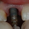
86. Subgingival cement accumulation Prepable abutment v The abutment is prepared so that the margin is slightly sub gingival. v An impression is made and the porcelain fused to metal crown was completed in a customary fashion. v The abutment is secured to the implant fixture and the crown is then cemented.
87. Subgingival cement accumulation Prepable abutment v The patient was unhappy with the esthetic result and so a hole was drilled into the occlusal surface in order to access the abutment screw. The crown and abutment was then removed v Note the accumulation of cement subgingivally.
88. Cement retained restorations Problem l Most dentists are not familiar with the proper technique to cement an implant crown given the fragility of the epithelial attachment l They attempt to use the same method they use with natural dentition (Wadhwani et al, 2012) Courtesy Dr. C. Wadhani
89. Subgingival cement accumulation ImplantSurface Bone EpitheliumSulcus Circumferential collagen fibers * Peri-implant tissues are more easily displaced from the surface of the implant crown implant. Why is there a greater risk of cement accumulation in the sulcus of implant crowns?
90. Cement retained restorations Strategies to limit embedding cement subgingivally l Avoid the use of stock (prefabricated abutments l Proper design of the custom abutment l Place the crown margin at or above the gingival margin l Venting ???? l Packing retraction cord prior to cementation ????? l Avoid the use of an excessive amount of cement
91. Strategies to limit embedding cement subgingivally Avoid the use of stock (prefabricated) abutments Considerations for use: v Tissue height should be essentially the same, 360 degrees around the abutment v Occlusal clearance for sufficient axial wall height for proper resistance and retention form v Angulation allows reasonable draw with adjacent teeth
92. Strategies to limit embedding cement subgingivally v Use custom abutments v Place the margins supra-gingivally
93. Strategies to limit embedding cement subgingivally Venting the restoration This is not an effective strategy. Venting helps the clinician seat the restoration but if the margin is subgingival cement is still injected deep into the sulcus (Wadhwani et al, 2012).
94. Strategies to limit embedding cement subgingivally Venting the abutment (Wadhwani et al, 2011) v Vent holes are placed 180 degrees from one another on the abutment above the level of the abutment screw head v With this design the excess cement flows into the chamber above the head of the abutment screw v Shows promise with bench studies Courtesy Dr. C. Wadhani
95. Strategies to limit embedding cement subgingivally Packing retraction cord into the cord prior to cementation § Gives the clinician a false sense of security § If the margin is sub- gingival, cement is still extruded sub-gingivally and often apical to the retraction cord
96. Strategies to limit embedding cement subgingivally Best strategy v Supra-gingival margins v Controlling the amount of cement used v Line the implant crown/s with teflon tape. The thickness of the tape mimics the thickness of the film thickness of the cement v Inject a fast set vinyl polysiloxane material into the intaglio surface of the crown. This will form a duplicate of the abutment v Remove the polysiloxane abutment duplicate and the teflon tape v Coat the inner surfaces of the implant crown/s with cement, seat the silicone abutment duplicate, remove the excess cement and seat the prosthesis into position intra-orally Courtesy Dr. C. Wadhani
97. Types of cements used v Polycarboxylate cements should not be used because they contain fluoride which will corrode the titanium surface of the implant or abutment. v Resin cements containing hydroxylated ethymethacrylate (HEMA) which is potent cytotoxic agent, should be avoided. v Zinc oxide and eugenol cements are favored. The are anti-bacterial and are radio-opaque.
98. Complications and trouble shooting Mechanical failures: Screw loosening v Rare with abutment size screws of modern designs and when they are tightened sequentially and with proper torque v More frequent with prosthetic size screws v These screws are of smaller diameter, finer thread patterns and are tightened to only 10-15 N/cm v We prefer not to use prefabricated (stock) abutments because the prosthesis is retained with these small screws
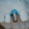
99. Complications and trouble shooting Mechanical failures: Screw fracture v Rare with abutment size screws of modern designs v More frequent with prosthetic sized screws v These screws are of smaller diameter Removal can be accomplished with an explore or a scaler. Some- times it helps to rotate the screw fragment deeper into the implant and then smooth over irregularities of the threads of the implant by means of a tap, or an impression coping etc. Courtesy Dr. N. AbouJaoude
100. Complications and trouble shooting Mechanical failures: Screw fracture Sometimes the internal threads of the implant must be retapped. A guide sleeve is useful when attempting this maneuver Guide sleeve Tap Courtesy Dr. N. AbouJaoude
101. Complications and trouble shooting v Usually seen in implants with unfavorable configurations, alignments and patients exhibiting parafunctional activity. v Note the unfavorable ratio between the length of the implants and the distance to the occlusal surfaces. Mechanical failures: Implant fracture (Courtesy Dr. N. AbouJaoude)
102. Unfavorable configurations, alignments and patients exhibiting parafunctional activity. Patient presents with: l Unfavorable ratios between the lengths of the implants and the distance to the occlusal plane, l Poor anchorage in grafted bone l Palatally positioned implants inclineed towards the buccal l A linear configuration Courtesy Dr. TL Chang
103. Design l Implant-assisted overlay RPD l Implants used for support and retention l Bracing (resistance to lateral forces) supplemented by the RPD design Unfavorable configurations, alignments Hader bar attachment ERA attachment Axis of rotation Courtesy Dr. TL Chang
104. l Implant connecting bar design is implant-assisted l Cross arch stabilization provided by the RPD design protects the implants from potentially detrimental lateral forces Unfavorable configurations, alignments Courtesy Dr. TL Chang
105. Complications and trouble shooting Mechanical failures: Implant fracture This is a five year followup x-ray of a patient with an implant supported fixed partial denture. Closer exam revealed both implants to be fractured . The patient was a heavy bruxer. Six months later he presented with significant bone loss around both implants.
106. This patient did well with this implant supported fixed partial denture for more than four years (note 4 year followup x-ray). However, soon thereafter, the anterior implant fractured, the bridge was removed and a trephine used to remove the implant. Complications and trouble shooting Mechanical failures: Implant fracture
107. Complications and trouble shooting The neck of this implant fractured during placement. Mechanical failures: Implant fracture Courtesy Dr. T. Tang
108. Complications and trouble shooting Fractured abutments • Rare except for zirconia abutments. • When they facture those with an internal connection are often difficult and time consuming to remove Courtesy Dr. A. Sharma
109. § Peri-implant mucositis: § A reversible inflammation of the soft tissues surrounding implants in function § Incidence: § Up to 38% of implants (Mir-Mari et al, 2012) § Treatment: § Removal of offending irritants (plaque, calculus, cement etc. § Local anti-microbial agents (Arestin, Atridox) (Trejo et al, 2006; Heitz-Mayfield et al, 2011). Complications and trouble shooting
110. • Peri-implantitis: • An inflammatory process affecting the tissues around and osseointegrated implant in function, resulting is loss of supporting bone Complications and trouble shooting Signs and symptoms v Bleeding upon probing v Granulation tissue formation v Purulence v Bone loss around the implants
111. • Peri-implantitis: • An inflammatory process affecting the tissues around and osseointegrated implant in function, resulting is loss of supporting bone Complications and trouble shooting Risk factors • Periodontitis • Smoking • Diabetes • Subgingival cement accumulations (80% according to Wilson et al, 2000) • Loose retaining screws
112. • Peri-implantitis: • An inflammatory process affecting the tissues around and osseointegrated implant in function, resulting is loss of supporting bone Complications and trouble shooting Incidence § Unknown primarily because of imprecise definitions used in the literature, multiple factors causing bone loss, etc.
113. l Peri-implantitis – an enigma. What is it really? Treatment l Usual conservative therapies l Removal of plaque, calculus, subgingival cement accumulations, chlorhexidine mouth rinses, and in nonresponders systemic antibiotics such as metronidazole and amoxicillin. l Plus instructions to check the occlusion for excursive contacts, loose screws, presence of foreign bodies, etc Complications and trouble shooting Courtesy Dr. D. Krill
114. l There is no evidence to indicate that bony reconstruction are successful or have any impact on treatment outcomes. Complications and trouble shooting Courtesy Dr. D. Krill
115. l Surgical debridement is recommended by some periodontists l Flaps are reflected to allow removal of retained cement, and decontamination of the implant surface l Some have attempted to reconstruct the bony defects with bone grafts l There is no evidence that this approach improves clinical outcomes Complications and trouble shooting
116. l According to one study, 80% of peri-implantitis cases are directly associated with retention of cement subgingivally Complications and trouble shooting
117. l Loss of keratinized tissue l Problematic around mandibular molars l Ounce of prevention is worth a pound of cure. Complications and trouble shooting Encourage the use of mucosal repositioning flaps during initial implant placement or during second stage surgery.
118. Recurrent loss of retention – cemented restorations l Insufficient height of axial walls can be due to: l Buccal or lingual inclinations l Lack of interocclusal space Complications and trouble shooting Secondary to inadequate retention and resistance form
119. Chipping and fracture of the laminated porcelain l Up to 22 % when the framework is zirconia l 8-10% when the framework is a ceramo-metal Complications and trouble shooting
120. Case report
121. Case report l This 49 year old, healthy female presented with multiple tooth loss in the posterior maxilla and wished to have these teeth replaced, preferably with implants. Loss of these teeth was secondary both to caries and periodontal disease. The mandibular dentition was mostly intact, but there were abnormalities in the occlusal plane in the molar region because of wear, super-eruption of molar teeth and unfavorable crown contours. The remaining maxillary posterior tooth exhibited advanced peridontal bone loss, with deep peridontal pockets and was clinically mobile. There was an impacted 3rd maxillary molar on the right side. There was no evidence or indication of parafunctional activity. The mandibular dentition was in good condition with minimal periodontal bone loss. Several crowns restoring the mandiblular molars had open margins but only minimal caries was noted. The maxillary sinuses exhibited varying degrees of pneumatization with insufficient bone to anchor implants (6-8 mm on the right and 3-8 mm on the left). The anterior maxillary and mandibular teeth were in good condition with significant vertical overlap and anterior guidance
122. Case report Major issues considered in this patient l Implant supported FDP vs. RPD l Socket augmentation l Sinus augmentation l Number and arrangement of implants l Screw retained vs cement retained prostheses l Do I need provisional restorations l Splinting vs nonsplinting l Occlusion – Anterior group function vs. group function
123. Case report
124. Case report l Provisional restorations
125. Case report l Custom abutments l Definitive restorations
126. Case report l Occlusion – Anterior group function l Patient is 15 years post delivery with virtually no loss of marginal bone l No chipping or fractures of porcelain
127. Case report
128. Case report This 71 year old healthy male presented with a failing fixed partial denture in the mandibular left posterior quadrant. The patient wished to replace these teeth with a fixed prosthesis. The fixed partial denture was failing, most probably because of the the extended span and the ratio of the number of dental units restored (5) in relation to the number of natural tooth abutments available (2) was unfavorable. The anterior abutment had fractured, probably due to the length of the span, and this tooth was nonrestorable. The maxillary arch was partially edentulous and several existing crowns exhibited caries at the margins. Teeth #15 and #29 had a questionable prognosis. The maxillary dentition exhbited little periodontal compromise but minimal pockets were found associated with the teeth of the posterior right quadrant. The discrepancies associated with the plane of occlusion were not clinically significant, but crown contours of the maxillary teeth were unfavorable. The posterior maxillary teeth on the left side were slightly extruded. Wear was moderate and there was evidence of parafunctional activity (bruxism). Oral hygiene was unsatisfactory. The posterior molar in the left mandible was tipped mesially and was unsuitable as an abutment for a fixed partial denture. However, it was periodontally sound and could be retained as an RPD abutment if the patient wished to pursue this form of treatment. The patient’s terminal dentition on the right side extended to the first molar. Exam revealed minimal bone loss of the edentulous segment in the left posterior mandible. The mandibular anterior teeth were crowded and exhibited root proximity. However, these teeth were positioned such that an anterior guided, mutually protected occlusal scheme was present and consistent with the patient’s envelope of function. Consequently, the patient did not wish to correct the arrangement of these teeth strictly for esthetic purposes.
129. Case report Issues considered in this case l Implant supported fixed dental prostheses vs removable partial denture (RPD) l Number and arrangement of implants l Cement retained vs screw retained prostheses l Cement retained vs screw retained prostheses l Occlusal materials l Occlusion – Anterior group function vs group function
130. Case report l Surgical drill (template) guide
131. Case report l Cement retention with custom abutments
132. Case report l Definitive restoration
133. Case report l Definitive restoration l Note the hygiene access
134. v Visit ffofr.org for hundreds of additional lectures on Complete Dentures, Fixed Prosthodontics, Implant Dentistry, Removable Partial Dentures, Esthetic Dentistry and Maxillofacial Prosthetics. v The lectures are free. v Our objective is to create the best and most comprehensive online programs of instruction in Prosthodontics
New Lectures
 Single Tooth Defects in Posterior Quadrants
Robert Faulkner, DDS
 Cement Retention vs Screw Retention
Robert Faulkner DDS, MS
 Prosthodontic Procedures and Complications
Robert Faulkner, DDS
 Angled Implants
Allesandro Pozzi, DDS