Implant Dentistry – Maxillary Defects – Course Transcript
- 1. Implants-Maxillary Defects John Beumer III DDS, MS Division of Advanced Prosthodontics, UCLA Mark T. Marunick DDSDirector, Maxillofacial Prosthetics, Wayne State University This program of instruction is protected by copyright ©. No portion of this program of instruction may be reproduced, recorded or transferred by any means electronic, digital, photographic, mechanical etc., or by any information storage or retrieval system, without prior permission.
- 2. 15. Implants – Maxillary Defects John Beumer III
- 3. Implant retained maxillary obturators Background Early failures Implant failure rates Bone loss Implant overload Evolution of tissue bar design Photoelastic analysis Implant sites Premaxilla Posterior alveolar ridge Maxillary tuberosity Zygoma Case reports Clinical data
- 4. Implant Retained Prostheses for Maxillary Defects l Maxillectomy defects – Challenge in edentulous patients: Stability, retention and support are compromised Implants can dramatically improve the stability and retention of the complete denture with obturator. Support must be provided by the residual palatal structures (palatal shelf, The forces of atmospheric alveolar ridge pressure, and adhesion and etc.) cohesion are no longer sufficient to keep the prosthesis in position
- 5. Retention is critical because without it:v Speech is hypernasalv Leakage of bolus and fluids into the nose occursv Mastication efficiency is compromised because the tongue is preoccupied with keeping the obturator is position
- 6. Masticatory Performance N=5 50.0 * * 46.2% performance 40.5 37.5 Defect 25.0 Intact 15.6 North 12.5 8.8 6.2 8.2 6.6 8.1 0 Entry Post-Surgery Post-CP Post-IP Garret et al, 2008
- 7. Retention is effective and the RPD design can be conservative if:The lateral wall of the defect is lined with skinA reasonable number of healthy teeth remain
- 8. Removable Partial Denture and ObturatorRetention: Provided by the lateral wall of the defect (oval)and the dentitionStability: Provided by the dentition, and the residual palatalstructuresSupport: Provided by the remaining dentition, residualpalatal shelf and alveolar process
- 9. Value of Implants• Retention provided onthe unresected side• Stability improvedwhich enhances retentionon the defect side(maintains properpositioning of theobturator in the defect) Result: Speech and swallowing restored Well retained prosthesis enables the patient’s tongue to position the bolus on the unresected side where residual denture bearing surfaces can provide support during mastication. Mastication is thereby restored to predisease levels of performance.
- 10. Early efforts yielded disappointing results What was the explanation for the bone loss?Most bone loss was found around implants placed in thepremaxilla and the least around solitary implants in the tuberosity.
- 11. Preliminary data –Success RatesImplant sites Number of implants placed Success Placed Uncovered Buried Failed %Anterior maxilla 26 *5 21 1 2 85.7Posterior maxilla 31 *8 14 **9 2 4 57.1Tuberosity 17 14 **3 0 6 57.1Pterygoid plates 4 4 **3 1 0 0Zygoma 4 4 2 0 50Palate 3 0 **3 0 0 -Total 85 *13 54 **18 6 12 66.7 At first glance this data is not particularly surprising. However, the degree of bone loss around implants placed in the premaxilla was disturbing (Roumanas et al, 1997).
- 12. Preliminary Data – UCLA Obturator Implant – Bone Levels: Implants in Function Minimum Moderate Severe Anterior Maxilla 5 4 8 Post. Maxilla 8 2 0 Tuberosity 8 1 1 A high percentage of implants placed in the anterior maxilla demonstrated moderate to severe bone loss while few of those under function in the posterior maxilla or the maxillary tuberosity demonstrated moderate to severe bone loss.What are the possible explanations for this difference?
- 13. Most implants in the tuberosity or posterior“0” ring attachments enabled the prosthesis to rotatein just about any plane. Result: Nonaxial forces delivered to the implant were minimized.
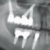
- 14. Tissue bar designs used in the premaxilla during this period were implant supported designs The design shown was commonly used in our clinic in the late 1980’s. Note the Hader bar extension in the distal extension area (arrow). In this position the Hader segment is performing like a nonresilient attachment. After 18 months of use, note the bone loss around the implants, particularly the distal implant adjacent to the cantilever. Our preliminary judgment was that the bone loss was secondary to implant overload.
- 15. Implant Overload and Bone Resorption Mechanisms of Implant Failure* Excessive occlusal loads Resulting microdamage (fractures, cracks, and delaminations) Resorption remodeling response of bone Increased porosity of bone in the interface zone secondary to remodeling Vicious cycle of continued loading, more microdamage, more porosity until failure Hoshaw et al, 1994; Brunski et al, 2000; Myamoto et al, 2008)
- 16. Eliminate Implant Overload inEdentulous Maxillectomy Patients Challenge: Develop implant assisted tissue bar designs specifically tailored for maxillectomy defects
- 17. Eliminating Implant Overload inEdentulous Maxillectomy Patients Goal:Create implant assisted designs. They should bedesigned to facilitate retention and stability. They should not be the sole means of support. Occlusal forces should be directed along the long axis of the implants.
- 18. Photoelastic AnalysisPurpose: To identify implant assistedtissue bar designs for use inmaxillectomy defects which provideadequate retention and best directocclusal forces along the long axis ofthe implants.
- 19. Photoelastic analysis*l Several designs were tested including: Hader bar Bar with ERA attachments with and without rests Bar with “0” ring attachments *Davis B, et al,1995
- 20. Photoelastic analysis Tissue bars for maxillectomy defects Results “0” Ring bar design Hader bar designThe “0” ring type attachment resulted in the most favorablestress distribution and the Hader bar type resulted in the leastfavorable stress distribution.
- 21. Photoelastic analysis – Results Tissue bar designsBest combination of retention and stressdistribution was associated with the tissue barwith ERA type resilient attachments on eitherside with occlusal rests atop the bar (arrows). Occlusal rests
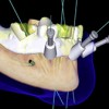
- 22. Maxillectomy defects Tissue bar designs Occlusal rests ERAERA Metal SubstructureERA attachments are connected toeach side and occlusal rests placedon top of the tissue bar.The rests control the axis of rotationand allow the ERA attachments tofunction vertically as designed.
- 23. Maxillectomy Defects – Tissue Bar Designs RestsThe metal substructure (arrow) only engages thebar via the rests and the ERA attachments. Thisdesign minimizes the lateral torquing forcesdelivered to the implants when occlusal forces areapplied and reduces the risk of implant overload.
- 24. Maxillectomy Defects – Tissue Bar DesignsSince we began using this design in themid 1990’s bone loss around the implantshas been almost totally eliminated.
- 25. Potential Implant Sitesl Residual premaxillary segmentl Residual posterior alveolar ridge Sinus lift and graftl Maxillary tuberosityl Zygoma Normal side Defect side
- 26. Premaxillary segmentBest bone sites although somemay have horizontal deficienciesrequiring onlay graftsPrincipal problem: Limited anterior– posterior spread ie, linearconfigurationsRetention bar designs must beimplant assisted Rentention bars with ERA attachments and occlusal rests are the preferred design
- 27. Maxillary tuberosityPoor quality bone – Fifty per cent of the implants withthe original machined surfaces placed failed toosseointegrate. The new microrough surfaces have hadvery little impact on these figures.This site used only when no others are available“0” Ring attachments are favored because they permitmultiple axis of rotation
- 28. Posterior alveolar ridgeProblems Limited bone in most patients because of pneumatized sinuses. Few patients present with sufficient bone over the sinus. In these patients implants 10 mm in length were placed. Rests
- 29. Posterior alveolar ridge a bTwo tissue bar designs for implants positioned in theposterior alveolus. One (a) uses ERA attachments withocclusal rests on either side of the bar. The other (b)uses Hader atttachments lined up parallel to theaccess of rotation in and out defect.
- 30. Posterior alveolar ridge Sinus lift and graft Predictable in patients with radical maxillectomy defects except when the the sinus region has been heavily irradiated.
- 31. Zygoma Implants in the zygoma on the resected side are not recommended Difficult hygiene access Implants must be placed in unfavorable angulations re: occlusal plane. High probability of implant failureA retentive skin lined defect,such as this one, provides justas much retention as implants,particularly if magneticattachments are used
- 32. Implants in the zygomaThe resected side – Problems The implants are located high in the defect, making oral hygiene difficult Implants are parallel to the plane of occlusion Consequently, only magnetic attachments can be used. The gains in retention with this type of attachment system are not significant
- 33. Implants in the zygoma The resected side – Problems Delivery 6 months post deliveryDifficult hygiene access lead to accumulation of plague.Result:Peri-implantitis, tissue hypertrophy, bone loss andeventually loss of the implants
- 34. Zygomaticus implants Best suited for total palatectomy defectsIssues l Radiation l Hygiene l Long term survivabilty Courtesy A. Sharma
- 35. Immediate placement upon tumor resection Useful in edentulous patients Reserved for patients with localized tumors
- 36. Immediate placement upon tumor resection In patients scheduled to receive postoperative radiation therapy the dose enhancement effect at the bone implant interface will compromise the vitality of the bone anchoring the implant.
- 37. Irradiation of existing implants- BackscatterSeveral months later and just after delivery of thetissue bar, the tissues on the labial surfaces of theimplants dehisced and the bone overlying the implantssequestrated leading to loss of the implants.
- 38. Implant Assisted Maxillary Obturators Case reportPatient is status post total palatectomy foradenoidcystic carcinoma. Three implants placed inmaxillary tuberosity.Note excellent skin lined undercut in left lateral wall ofdefect
- 39. Case report Tissue bar design used. The anterior Hader bar attachment (oval) was oriented parallel to the estimated axis of rotation. The posterior Hader segment (arrow) was designed to facilitate stability.The anteriorimplant failed tointegrate andwas removed.
- 40. Case reportThe finished obturator prosthesis The posterior Hader clip was made to be nonretentive Note the nasal aperture extensionTwo and one half years after delivery, anterior implant failed.Failure was preceded by steady, progressive bone loss. Loss wasprobably caused by long lever arm of prosthesis leading toimplant overload.
- 41. Case report “0” ring secured to remaining implant. Eight years later implant is still present with no significant bone loss. Why? The “0” ring permits rotation around just about any axis, whereas previous design permitted rotation around just one axis.Result: The magnitude of lateral torquing forcesdelivered to the implant is minimized with the “0”ring attachment.
- 42. Total palatectomy restored using implants Speech and swallowing were restored.Retention: The implant The lateral wall of the defect The nasal aperture extension
- 43. Case report-Soft Palate Defect The completed prosthesis in The completed position. complete denture and obturator Retention was excellent and speech, mastication, and swallowing were restored.
- 44. Case Report – Combined Hard and Soft Palate Defect This patient is S/P maxillectomy. The soft palate has also been resected. The anterior teeth were lost secondary to periodontal bone loss. Implants were placed in the residual premaxillary segment.
- 45. Case Report – Hard and Soft Palate DefectThe tissue bar is tried must fit passively.Rests (arrows) are milled into the bar between the implants.Occlusal forces are directed through the rests
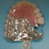
- 46. Case Report – Hard and Soft Palate Defect Rests ERAAttachments Note the metal substructure incorporated within the finished prosthesis. It contains the ERA attachments and the occlusal rests.
- 47. Case ReportNote contours of obturator.Extension into velopharyngealarea is about 10 mm in height.Note prominent gingival rollposteriorly on defect side todeflect the cheek away from thbiting surfacesProsthesis in position. Noteelevation of right lateral incisorand cuspid so as to follow lip line.
- 48. Total Palatectomy Defectsv Conventional length vs zygomaticus implants v Total palatectomy secondary to mucormycosis v Skin graft at revision surgery v Two 10mm dental implants placed in each zygoma Courtesy R. Wallace
- 49. Prosthetic Considerationsl Findings: l Bilateral total maxillectomy, all nasal bones removed, skin graft l Collapsed midfacial contours l 4 Max 3.75mm x 10mm dental implants in zygomatic bones, severe misangulation l Opposing natural dentition l Catawampus occlusal plane
- 50. Prosthetic Considerationsl Treatment Plan: l 2 cast implant tissue bars w/ magnetic attachments l Maxillary implant & soft palate retained complete denture obturator l Surgical release of anterior scar band l Maxillary obturator hard reline
- 51. Total Palatectomy Defects
- 52. Fixture Level Impression
- 53. Tissue Bar Design
- 54. Soldered Connectors
- 55. Altered Cast Functional
- 56. Altered Cast Functional
- 57. Artificial Tooth Arrangement
- 58. Definitive Prosthesis
- 59. Definitive Treatment
- 60. Definitive Treatment
- 61. Definitive Treatment
- 62. Post-Treatment Frontal View
- 63. Case Report – Bilateral Maxillectomy 14-yr old female patientPMH: v Dx with Acute Lymphoblastic Leukemia (ALL) when 4-yr old v A series of chemotherapy (Methotrexate, Vincristine, 6MP) over 21/2 years for the control of ALL
- 64. Case report – 3 (cont’d) PMH: v Develop Mucormycosis in her palate at 2-wk of chemotherapy v Multiple debridement over several months, resulting bimaxillary resection v Attempted palatal reconstruction with a rib graft without success v Maintained oral function with an obturator prosthesis; a single remaining tooth (#8) served as an abutment; however, the obturator function was lost when the tooth was removed from progressive decay
- 65. Clinical examinationv Absence of central aspects of the Rt/Lt maxilla, foreshortened nasal septum along with its anatomic structures, hard and soft palates, pyriform aperturev No skin graft in the lateral wall of defectv Superior surface lined with nonkeratinized mucosa
- 66. Treatment Planv Placement of osseointegrated implants to provide retention, stability and support of a new obturatorv However, inadequate bone volume in the midfacial skeleton for implant placement
- 67. Distraction osteogenesis for vertical bone augmentationBilateral extraosseous Track distractors (KLS Martin) on the remaining maxilla: v Lengthen the midfacial bony remnants v Provide temporary retention of the obturator prosthesisAfter a 1-week latency healing period, distraction was initiated at a rate of 1 mm/day (0.3 mm for 1 turn).
- 68. Bone graftingv Removal of the distractorsv Augmentation of the anterior maxillary ridge with posterior iliac cortical cancellous onlay graftv Placement of 4 immediate provisional implants for obturator management: Lost 2
- 69. Placement of Osseointegrated ImplantsPlaced seven: 4 uncovered, 2 buried, 3 lost (2 uncovered/lost) v #1 site: 4.0 x 15 mm (Buried) v #2 site: 3.75 x 13 mm (Uncovered) v #6 site: 3.3 x 13 mm (Uncovered/Lost) v #7 site: 3.3 x 10 mm (Uncovered/Lost) v #10 site: 3.25 x 13 mm (Lost) v #11 site: 3.75 x 10 mm (Uncovered) v #16 site: 4.0 x 18 mm (Buried)
- 70. Abutment connection and Magnetic attachmentsv UCLA abutments: customized for soft tissue thicknessv Magnetic keeper (Magfit DX) were cemented to the superior surface of the abutment using resin cement (Panavia F2.0)
- 71. Custom tray Index Custom trayv Replica of existing obturator as a custom trayv Align magnetic couplesv Pick-up one part of the magnets to the custom tray, using GC pattern resinv Implants and magnets provide support and retention of the tray
- 72. Impressionv Border molding, using ISO impression compoundv Dynamic impression, using tissue conditioning materialv (Visco-gel)
- 73. Record basev Master cast with magnetic couplesv A layer of wax adaptationv Process record base, using heat- activated acrylic resin (Lucitone 199) at 165°F for 9 hrs
- 74. Wax rim and teeth sep-upv Try-in the processed record basev Build-up occlusal rim and symmetric contouring of the Wax rim palate, using baseplate waxv Jaw relation record, mount on an articulator and denture teeth set- up
- 75. Try-in:v Phonetics, esthetics, lip supportv Fashion the palatal contour based on phonetics, utilizing PIPv Waxing and festooning of the gingival and palatal portions
- 76. Completed Front obturatorv Process the obturator into heat-activated acrylic resin Lateral (Lucitone 199) at 138°F for 12 hrs Posterior Palatal
- 77. Deliveryl Esthetic and functional fitting v Remount for occlusal equilibration v Oral hygiene instruction v Regular recall appointments
- 78. Challenge in Edentulous Maxillectomy Defects: For the prosthodontist: Develop tissue bar designs for radical maxillectomy defects that: Account for the multiple axis of rotation Direct occlusal loads along the long axis of the implants Do not overload the implants when occlusal forces are applied to the prosthesis Provide effective retention on the normal side For the head and neck surgeon: To create maxillectomy defects with retentive qualities so as to counteract the forces of gravity and provide retention and stability on the defect side.
- 79. Masticatory Performance N=5 50.0 * * 46.2% performance 40.5 37.5 Defect 25.0 Intact 15.6 North 12.5 8.8 6.2 8.2 6.6 8.1 0 Entry Post-Surgery Post-CP Post-IP Garret et al, 2008
- 80. Implants in edentulous maxillectomy patients Patients Number of implants Success Treated placed uncovered buried failed %Irradiated 13 50 29 3 10 55.2Non-Irradiated 10 35 25 3 2 80.0Totals 23 85 54 6 12 66.7 Failures in the irradiated group tend to be late, after the implants have been loaded.
- 81. Implants in Maxillectomy Defects Lessons LearnedImplants should not be the sole means ofretention, stability and supportThe residual palatal structures should beengaged effectivelyThe defect should be used to maximumadvantage to retain, stabilize and supportthe obturator prosthesis
- 82. v Visit ffofr.org for hundreds of additional lectures on Complete Dentures, Implant Dentistry, Removable Partial Dentures, Esthetic Dentistry and Maxillofacial Prosthetics.v The lectures are free.v Our objective is to create the best and most comprehensive online programs of instruction in Prosthodontics
New Lectures
 Cement Retention vs Screw Retention
John Beumer III DDS, MS
Robert Faulkner DDS, MS
Robert Faulkner DDS, MS
 Restoration of Posterior Quadrants and Treatment Planning
John Beumer III DDS, MS
Robert Faulkner, DDS
Kumar C. Shah DDS, MS
Robert Faulkner, DDS
Kumar C. Shah DDS, MS
 Computer Guided Treatment Planning and Surgery
John Beumer III DDS, MS
Allesandro Pozzi, DDS
Robert Faulkner DDS
Allesandro Pozzi, DDS
Robert Faulkner DDS
 Implants and RPDs
John Beumer III DDS, MS
Ting Ling Chang DDS
Robert Faulkner DDS
Ting Ling Chang DDS
Robert Faulkner DDS