Since the introduction of these implant systems there has been an explosion of new components, terminology and procedures. A whole new language has evolved dealing with implant fixtures, custom abutments, transfer impression copings, guide pins etc. The purpose of this program is to define these terms and demonstrate how each of the implant components is utilized.
Implant Dentistry – Dental Implant Components and Basic Techniques — Course Transcript
- 1. 3. Implant ComponentsHistory, New Developments and Basic Prosthodontic Procedures George R. Perri DDS Division of Advanced Prosthodontics, Biomaterials and Hospital Dentistry UCLA School of Dentistry
- 2. Osseointegrated Implants Implant Components History, New Developments and Basic Prosthodontic Procedures George R. Perri DDS Division of Advanced Prosthodontics, Biomaterials and Hospital Dentistry UCLA School of Dentistry This program of instruction is protected by copyright ©. No portion of this program of instruction may be reproduced, recorded or transferred by any means electronic, digital, photographic, mechanical etc., or by any information storage or retrieval system, without prior permission.
- 3. ComponentsCategories 1. Fixtures / Implants 2. Abutments n Healing n Basic n Custom 3. Gold cylinders 4. Analogs / Replicas n Abutment n Fixture Original Implant Pillar 5. Impression copings 6. Connection Armamentaria n Screw drivers n Guide pins
- 4. FixtureFixture / Implant 1. Titanium 2. Different Configurations n Threaded and Non-threaded n Cylindrical and Tapered 3. Different Surfaces n Machined Surface n Enhanced Surface 4. Different Widths n Narrow, Regular and Wide Platforms Original Brånemark Style 5. Different Heads Hex-headed Implant n External and Internal
- 5. FixtureOriginal Threaded Fixture n External hex headed n Original Brånemark had only a machined surface. n Newer versions have an “enhanced” surface. n Lengths 7-20 mm in regular platform n Widths / Platforms: n Narrow: 3.3mm n Regular: 3.75 and 4.0 mm n Wide: 5mm
- 6. ReplaceSelect™ New Tri-channel Internal Connection
- 7. Replace Implant System n Enhanced Surface n Two implant designs: n Unique anatomic “tooth root” shape n Classic cylinder n Internal Connection
- 8. Replace Select Tapered ImplantImmediate placement into extraction socketsAnatomic advantages with taperEase of achieving initial stabilityImmediate loadingEsthetic restorative componentsSimplified placement (including staff responsibilities)
- 9. Implant Evolutionn Implant options now include 1.5 and 3.0 mm collars. Implant threading / surface treatment to bottom of collarn Newest generation has surface treatment to top of implant: No polished collar.
- 10. Four Diameters3.5mm 4.3mm 5.0mm 6.0mm2.4mm 2.7mm 3.25mm 3.8mm Replace Select Implants
- 11. Straumann implants! Standard Standard Plus Tapered Effect
- 12. Straumann implants
- 13. Standard implants 4.8 mm 4.8 mm 4.8 mm 6.5 mm 3.3 mm 4.1 mm 4.8 mm 4.8 mmS Ø 3.3 mm S Ø 4.1 mm S Ø 4.8 mm S Ø 4.8 mm WNRN RN RN
- 14. Standard Plus implants 3.5 mm 4.8 mm 4.8 mm 4.8 mm 6.5 mm 3.3 mm 3.3 mm 4.1 mm 4.8 mm 4.8 mmSP Ø 3.3 mm SP Ø 3.3 mm SP Ø 4.1 mm SP Ø 4.8 mm SP Ø 4.8 mm NN RN RN RN WN
- 15. Tapered Effect implants 4.8 mm 4.8 mm 6.5 mm3.3 mm 4.1 mm 4.8 mm
- 16. Straumann’s 8° Morse taper connection • Proven validity and function since 1986 • Loosening torque slightly higher than tightening torque • Proven resistance against long-term cyclic loading • Standardized tightening torque of 35 Ncm • 91% of functional load transferred into Morse taper for optimal load distribution • Stability against rotational loosening Sutter et al. 1988/Schroeder et al. 1996/Norton 199
- 17. Morse taper! Non-rotation through mechanical lock: 8° or less will yield a mechanically locking friction fit
- 18. Morse taper connection!• 8° Morse taper absorbs 91% of • Thread only takes the functional 9% of the load functional load!
- 19. Prosthetics !Regular neck implants and abutments
- 20. Solid abutments! RN 4.0 mm RN 5.5 mm RN 7.0 mm WN 4.0 mm WN 5.5 mm RN (Regular Neck) WN (Wide Neck)
- 21. synOcta® prosthetic system!• Abutment selection on the model!• Implant level impression capability!• Provisionalization !• Custom abutment!
- 22. synOcta® abutments WN (Wide Neck) RN (Regular Neck)
- 23. Indications for Narrow Neck Implants • Single tooth replacement • Maxilla: lateral incisors • Mandible: central/lateral incisors • Minimal space (5.0 mm) Abutment Possibilities For screw-retained For cement-retained
- 24. Abutmentsn RestorativeAbutment allows connection of the restoration to the implant.n Themany different types of abutments facilitate the restoration of implants.
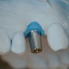
- 25. Healing Abutmentn Maintains an opening through the soft tissue during treatment, allowing easy access to the fixture.n Not useable to make the final restorationn One Piece Construction: n Screw and Abutment in one n No Inferior hexn Value in polished tapered design.
- 26. Basic AbutmentsStandard Abutment n Titanium n Cylindrical Shape n Internal hex on bottom matches hex on fixture to prevent rotation. n Designed to be supra- gingival and non-esthetic n No emergence profile n Useful for Hader Bars and FBAB.
- 27. Basic AbutmentsStandard Abutment n Lengths 3 to 10 mm n Separate Abutment Screw and Abutment Body n The gold screw screws into the abutment screw head
- 28. Basic AbutmentsStandard Abutment n Healing Cap n Protects head of abutment during treatment phase. n Helps control soft tissue during healing
- 29. Basic AbutmentsEstheticone Abutment n Conical Abutment n Titanium n Hexed connection to fixture. n Collar widths of 1, 2 & 3 mm n Improves esthetic potential of restoration.
- 30. Basic AbutmentsEstheticone Abutment n Separate Abutment Screw and Abutment Body
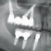
- 31. Basic AbutmentsEstheticone Abutment n Seating of the abutment must be verified with an x-ray. n Design of abutment allows up to 30° non parallelism of fixtures
- 32. Basic AbutmentsEstheticone Abutment n Healing Caps n Protects the head of the abutment during restorative phase n Helps control soft tissue n During healing n During restorative phase keeps tissue from collapsing over the subgingival margin
- 33. Basic AbutmentsAngulated Abutment n Titanium n Corrects screw access for mal-aligned implants, but doesn’t improve implant loading. n Internal 12 positions on bottom matches hex on fixture to prevent rotation and give multiple angle correction possibilities. n Can be difficult to use esthetically. n Same healing cap / gold cylinder as the estheticone
- 34. Basic AbutmentsMirusCone Abutment n Shorter height than Estheticone abutment Allows 40º misalignment n Allows greater degree of non- 20º parallelism with fixture 40º placement- up to 40°.MultiUnit Abutment n Same dimensions as MirusCone n No hex under abutment to facilitate placement n Only for bridges n Strengthened Abutment Screw NP 1-7mm RP 1-9mm WP 1-7mm
- 35. Gold CylinderGold Cylinder 1. Different cylinders for different abutments. 2. Cylinders become incorporated into the final restoration 3. Since it is pre-made and with a machined interface toward the abutment, the consistency of fit is improved over a custom casting
- 36. Gold CylinderStandard Abutment Gold Cylinder: n 3 and 4 mm heights n Held in place by a gold screw. n Slotted n Hexed n Underside is non-hexed: for multiple units “bridges” only. n Restoration is waxed and cast around the gold cylinder.
- 37. Gold CylinderEstheticone Abutment Gold Cylinder n Only contact is on margin of abutment. n Same cylinder is used for angled abutments.
- 38. Custom AbutmentsCustom Abutment Types: 1. UCLA: Gold cylinder to fixture n Hexed- Engaging n Non Hexed – Non Engaging 2. Set margin with impression cap n i.e. the “easy abutment” 3. Prepable n Titanium: n Cemented final restoration n Straight Esthetic n Angled Esthetic n Ceramic n Cemented final restoration n Screw retained 4. Procera n Titanium n Alumina n Zirconia 5. Provisional to fixture (acrylic / composite)
- 39. Custom AbutmentsUCLA Abutment n Allows connection of the restoration directly to the fixture. n Combines abutment, gold cylinder and restoration into one. n Uses include: n Esthetics n Limited Interocclusal space n Angulation Correction n Custom Substructures
- 40. Custom AbutmentsUCLA Abutment n Original UCLA Abutment was a plastic castable pattern. n Improved consistency of fit was developed with the introduction of a precast and machined abutment with a waxing sleeve. n Two types n Hexed / non-rotational for a single tooth n Non hexed for bridges
- 41. Hexed UCLA Abutment Screw-retained GoldAdapt™ (engaging) & Cemented Restorations Gold Cylinder to Fixture (engaging) NP/RP/WP Single tooth and multiple unit restorations “UCLA” type abutment: wax/invest/cast • When interarch space is limitedHexed • When the fixture angulation is not acceptable • Follows contours of the soft tissue • Conventional restorative technique UniGrip Minimum interarch space required: .5mm 3.5mm Ø3.7mm (NP) Ø4.3mm (RP) Ø5.3mm (WP)
- 42. Non-Hexed UCLA Abutment Screw-retained ™ (non-engaging) Restorations GoldAdapt Gold Cylinder to Fixture (non-engaging) NP/RP/WP Multiple unit restorations “UCLA” type abutment: wax/invest/cast • When interarch space is limited UniGripNon-hexed Minimum interarch space required: 3.5mm .5mm Ø3.7mm (NP) Ø4.3mm (RP) Ø5.3mm (WP)
- 43. UCLA Abutment – Clinical Procedure Custom Abutment -Substructure and One Piece Restoration Optional (Recommended for WP)Wax/Invest Screw- retained- One Piece Bake porcelain Restoration Gold alloy directly to Casting Abutment
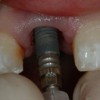
- 44. UCLA Abutment: Lingual Screw Access
- 45. Easy Abutment‘Easier than Crown & Bridge’n pre-defined marginn get to use an impression coping Available in: 4.3, 5.0 & 6.0
- 46. Easy Abutment with Healing Cap
- 47. Easy Abutment with Screw Access Plug in place – No modification of the Easy Abutment was required in this case.
- 48. Easy Abutment Snap-onImpression Cap in place.
- 49. Impression material is injectedinto the Snap-on Impression Cap.
- 50. The Snap-on Impression Cap is captured in the impression.
- 51. An Easy Abutment Analog maybe used if the abutment has notbeen modified. Note the accurate impression of the sub-gingival margin.
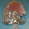
- 52. A standard soft-tissue model is fabricated.
- 53. Pre-fabricated Plastic Cap Copings may be usedif the Easy Abutment has not been modified.
- 54. The restoration is completed usingstandard crown & bridge procedures.
- 55. The final restoration…
- 56. …is cemented in place withImProv™ temporary cement.
- 57. Titanium Prepable Esthetic™ NP/RP/WP Cemented Restorations Single tooth and multiple unit restorations Prepable “pre-machined” titanium abutment • Follows contours of the soft tissue • Conventional restorative technique NP 2.7mm NP 11mm RP 2.8mm RP 8/11mm WP 3.2mm 11mm WP 8/11mm 1.4mm 11mm 2.8mm 1.5mm 15° NP Ø4.5mm RP Ø5 – 7mm WP Ø6 – 8mm 25° Straight RP only
- 58. Titanium Prepable Esthetic – Clinical ProcedureAbutment prepared onthe master cast Optional (Recommended for WP)
- 59. Ceramic Esthetic AbutmentScrew-retained All Ceramic™ RP & Cemented Restorations Single tooth and multiple unit restorations All ceramic abutment for optimal esthetics • When fixture placement is too coronal • When there is thin gingival tissue • Preparation follows contours of the soft tissue • Conventional restorative technique 6mm Now with UniGrip! Torque4.1mm without deforming 12mm 2mm Square UniGrip Retentive connection
- 60. Ceramic Abutment – Procedure Porcelain baked directly to Abutment Abutment prepared on the master cast Screw- retained Alternative: Porcelain baked directly toOptional abutment
- 61. Cemented RestorationsProcera® Abutment NP/RP/WP Single tooth and multiple unit restorations Custom Titanium abutment Custom Alumina Custom Zirconia Follows contours of the soft tissue Conventional restorative technique
- 62. Advanced Uses for Custom UCLA ABUTMENTSn Custom abutment substructures n Separateunits n Linked units
- 63. Custom Abutment Sub-StructuresIndications n Misaligned implant fixtures n Elimination of screw access hole from the occlusal surface n Control the thickness of metal and porcelain in an anterior restoration n Develop proper emergence profiles
- 64. Custom Abutment Sub-Structuresn A UCLA abutment allows the development of a custom shaped substructure: n SeparateUnits n Linked Abutmentsn Canallow the final restoration to be cemented or screw retained (with a lingual set-screw).
- 65. UCLA Abutment Custom Sub-Structure: Angle Correction- Lingual set screw
- 66. Custom Abutment Sub-Structures: Separate Units Begin with full contour wax-up using a UCLA abutment (AuAdapt). Note the buccal angulation of the implants.
- 67. Custom Abutment Sub-Structures: Separate Units Abutments are prepared with a three degree taper. Note the channel prepared for the lingual access retaining set screw.
- 68. Custom Abutment Sub-Structures: Separate UnitsEach abutment is designed to engage the hex on top of the implant fixture. Note the change in angulation created by the abutments. Note lingual set screw channels
- 69. Custom Abutment Sub-Structures: Separate Units
- 70. Custom Abutment Sub-Structures: Separate Units Final prosthesis in position. These restorations can be either screw or cement retained.
- 71. Custom Abutment Substructures: Linked Abutmentsn Supra-structure will fit with confidence intraorally if it fits in the labn More predictable sharing of load between implantsn Less chance an abutment screw may loosen
- 72. Custom Abutment Substructures: Linked AbutmentsThe implants placed in the right mandible were inclined towards the lingual
- 73. Custom Sub-Structures: Linked Abutments This technique permits the clinician to control two key occlusal factors – width of the occlusal table, and the cusp angles.Result: Reduced load magnification and less chance of implant overload.
- 74. Custom Abutments *Note width of the occlusal table*Note size of the embrasures
- 75. Provisionalsn Provisional cylinders exist which can substitute for all available gold cylinders with conventional abutments.n There are also provisional cylinders that attach directly to the fixture like a UCLA abutment.
- 76. Provisionalsn Use of a provisional UCLA abutment allows addition of acrylic for the development of a provisional that connects directly to the fixture without a separate abutment.
- 77. Provisional RestorationsPrimary Uses: n Esthetic Issues n Soft tissue n Tooth shape / form. n Prosthesis design issues. n Identify angulation problems that may affect the definitive restoration. n Gain patient approval of esthetics/function before investing in final.
- 78. Analogs / ReplicasAnalogs allow the accurate transfer of a facsimile of the intraoral component to a working model.
- 79. AnalogsAbutment Analogs n Allows creation of a model with the same characteristics as a given intraoral abutment.
- 80. AnalogsFixture Analogs n Allows creation of a model with the same characteristics as a given intraoral fixture.
- 81. Impression Copings1. Abutment Level2. Fixture Level3. Linked Impression Copings
- 82. Impression CopingsAbutment Level: Open and Closed Tray Copings n Aspecifically matched coping is needed for each differently shaped abutment.
- 83. Impression Copingsn Open Trayn Pick Up Are different names for then Square same type of coping.
- 84. Impression Copings n Open TrayAbutment Level: n Pickup n Square n A square coping is “locked” into the impression due to their shape. n Screwed to abutment with guide pin. n Impression made with “open” tray. n Analogs are attached before pouring the master model.
- 85. Impression Copingsn Closed Trayn Transfer Are different names for then Tapered same type of coping.
- 86. Impression Copings n Closed TrayAbutment Level: n Transfer n Tapered n Screw to abutment n Take impression with closed tray n Remove Impression n Unscrew copings n Attach to analogs n Replace coping into impression and pour.
- 87. Impression CopingsFixture Level Impression Coping n Impression is made directly to the fixture- No abutment is in place. n X-ray is always necessary to verify seating n Coping can be Open or Closed Tray n The fixture level impression is required for a fixture level “UCLA”restoration and for extraoral abutment selection.
- 88. ImpressionsFixture Level- Open Tray n Registers both position of fixture and orientation of the fixture hex. n Becomes locked into the final impression so an open tray is needed. n After the tray is removed a fixture analog is connected and the model poured
- 89. Fixture Level- Open Tray
- 90. Impression CopingsFixture Level- Closed Tray n Shape allows it to remain in mouth when impression is removed-uses a flat head screw giving it a tapered shape n Two piece coping will still allow registration of Hex
- 91. Impression CopingsFixture Level- Closed Tray n Shape allows it to remain in mouth when impression is removed-uses flat head screw n Two piece coping will still allow registration of Hex n Single piece coping is only for bridges (no hex registration)
- 92. By utilizing the flat head screwChanging Pick-up to instead of a guide-pin, the same impression coping can Transfer Coping be used as a closed tray coping instead of an open tray impression coping Flat Head Screw Guide Pin Pick-up / with guide pin
- 93. Master CastsHow do we know they are accurate?
- 94. Castings – Passive Fit DEVELOP A CORRECT MODEL FIRST or Plan to solder after try in of units Reduces risk of implant overload
- 95. Impression CopingsLinked Copings n Long history of use n Behaves as pick-up impression coping n Accuracy with original techniques limited by materials used
- 96. n Remove index from mouth and pour aImpression Copings registration in quick set intra oral plaster type IILinked Copings before taking final impression. n Useful in impression taking to improve accuracy of impression n Can be fixture or abutment level
- 97. Impression Copings
- 98. Impression CopingsLinked Copings n Useful to prove accuracy of final Impression
- 99. Impression Technique 2Advanced Technique n Make a Custom Tray around any model… preferably one that shows the healing abutments. n Keep it close to the tissue in the area that the holes for the impression copings are made.
- 100. Impression Technique 2Advanced Technique n Replacethe healing abutments with the pick up style fixture level impression copings
- 101. Impression Technique 2Advanced Technique n Make sure the tray will seat without touching the impression copings n Take a regular final impression but remove any impression material from the copings n Lute the copings to the tray with GC pattern resin
- 102. Impression Technique 2Advanced Technique n Carefully unscrew tray from mouth and add analogs n Carefully pour master model
- 103. Impression CopingsLinked Copings n Directly connect the copings intraorally with triad or flowable composite n Section and re- lute the copings as necessary n Pickup impression
- 104. Connection ArmamentariaScrew Drivers
- 105. ConnectionAbutment Holders n Counter rotation device
- 106. ConnectionTorque Drivers n Allowthe connection to be made with the correct pre- load
- 107. ConnectionLaboratory Guide Pins n Goldscrew size n Abutment screw size
- 108. Selected Referencesn Binon P. Implants and components: Entering the new millennium. Int J Oral Maxillofac Implants 15:76-94, 2000
- 109. Coming soonv Edentulous Mandible – Overlay Denturesv Edentulous Maxilla – Overlay Dentures
- 110. v Visit ffofr.org for hundreds of additional lectures on Complete Dentures, Implant Dentistry, Removable Partial Dentures, Esthetic Dentistry and Maxillofacial Prosthetics.v The lectures are free.v Our objective is to create the best and most comprehensive online programs of instruction in Prosthodontics
New Lectures
 Cement Retention vs Screw Retention
John Beumer III DDS, MS
Robert Faulkner DDS, MS
Robert Faulkner DDS, MS
 Restoration of Posterior Quadrants and Treatment Planning
John Beumer III DDS, MS
Robert Faulkner, DDS
Kumar C. Shah DDS, MS
Robert Faulkner, DDS
Kumar C. Shah DDS, MS
 Implants and RPDs
John Beumer III DDS, MS
Ting Ling Chang DDS
Robert Faulkner DDS
Ting Ling Chang DDS
Robert Faulkner DDS
 Single Tooth Defects in Posterior Quadrants
John Beumer III DDS, MS
Robert Faulkner, DDS
Robert Faulkner, DDS