The original implant systems used abutments to unite the dental restoration with the implant fixture. These components were all screw retained. Since then a number of new abutment systems have been introduced in order to enable fabrication of esthetically pleasing restorations and to overcome positional and angulation problems. In recent times cemented type restorations have become popular. The purpose of this program is to review some of the options available and to address the current debate being waged being screw retained restorations and cement retained restorations.
Implant Dentistry – Abutment Selection — Course Transcript
- 1. 9. Abutment selection John Beumer III DDS, MS George Perri DDS Division of Advanced Prosthodontics, Biomaterials and Hospital Dentistry, UCLAThis program of instruction is protected by copyright ©. No portion ofthis program of instruction may be reproduced, recorded or transferredby any means electronic, digital, photographic, mechanical etc., or byany information storage or retrieval system, without prior permission.
- 2. Restoration connection to abutment and/or implant fixture Biologic and technical issues v Screw retained systems v Cement retained systems v Screwless – cementless system (UCLA II) v Platform reduction (ie platform switching)
- 3. Arguments commonly used in favor of cementationv It’s a common procedure in the dental office: No “Implant” knowledge necessary? v Implants for dummiesv The screw access hole is through the labial or buccal v Other options – Lingual set screws-lab expense and lab expertisev Simple traditional impression techniques? v Packing gingival retraction cord vs screw retained impression copingsv Better esthetics? v Permits the use of zirconium abutments. Predictability of Zirconium abutments?v Fit isn’t as critical v Really? The assumption is that a misfit is just a passive cement gap with no negative consequences
- 4. Major Problemsv Cement accumulationv Lack of retrievability
- 5. Subgingival cement accumulationPrepable abutment These abutments can be prepared at the lab bench or intraorally. An impression is made and the restoration is cemented in the usual and customary fashion.
- 6. Subgingival cement accumulationPrepable abutment An impression was obtained with an impression coping and the prepable abutment was attached to the fixture analogue imbedded in the master cast.
- 7. Subgingival cement accumulationPrepable abutmentv The abutment is prepared so that the margin is slightly sub gingival.v An impression is made and the porcelain fused to metal crown was completed in a customary fashion.v The abutment is secured to the implant fixture and the crown is then cemented.
- 8. Subgingival cement accumulationPrepable abutmentv The patient was unhappy with the esthetic result and so ahole was drilled into the occlusal surface in order to access theabutment screw. The crown and abutment was then removedv Note the accumulation of cement subgingivally.
- 9. Subgingival cement accumulation Sulcus Epithelium Implant SurfaceWhy is there a greater risk ofcement accumulation in thesulcus of implant crowns?Peri-implanttissues aremore easilydisplaced from Circumferentialthe surface of collagen fibersthe restoration. Bone *
- 10. Anatomy & Biology of Peri-Implant Soft TissueSimilarities betweenperiodontal & peri-implant soft tissues:v Oral epitheliumv Sulcular epitheliumv Junctional epitheliumDifferences in peri-implantsoft tissues include:v Lack of CT attachmentv Hypovascular, hypocellular CT zone adjacent to the implantv Absence of periodontal ligament blood supply Sclar AG, 2003
- 11. Cementation permits use of a ceramic abutment Excellent esthetic resultv Subgingival cement accumulation can be limited by packing gingival retraction cord prior to cementationv Allows the creation of an all ceramic restoration from the implant to the incisal edge. Is there an esthetic advantage? Perhaps.v The main issue is positioning of the cement marginv Incidence of fracture of zirconium abutments is a concern but long term followup data is not yet available.
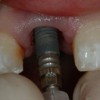
- 12. Preformed nonprepable abutmentsIssues of concern v Positionof the cement margin in relation to the gingival margin v Particularly significant in the anterior region v Impaction of cement into the gingival sulcus v Difficulty in seating the crown because of hydraulic pressure
- 13. Preformed nonprepable abutmentsConsiderations for use:v Tissue height essentially the same 360 degrees around the abutmentv Head of the implant or abutment cement margin just subgingivalv Sufficient clearance for sufficient axial wall height for predictable cement retentionv Angulation allows reasonable draw with adjacent teeth
- 14. Preformed nonprepable abutmentsv The margin between the crown and the abutment does not follow the gingival margin.v There is significant risk of trapping cement beneath the gingival tissues upon cementation.
- 15. Preformed nonprepable abutments This patient presented with severe peri-implantitis 3 years post insertion of the crown. The initial x-ray A subsequent appeared to x-ray, taken at indicate that the right angles to crown was the long axis of seated. the implant, revealed that the crown, was not seated.Inability to completely seat the crown onto the abutment is acommon complication associated with preformed abutments.Lingual access holes may help relieve the hydraulic pressure andenable seating of the crown.
- 16. Preformed nonprepable abutmentsNote the inflammationassociated with the peri-implant gingiva 2 1/2years post insertion.
- 17. UCLA Abutment Indications: a) Lack of interocclusal space b) Restorations in the esthetic zone c) Angulation problems d) Soft tissue problems
- 18. UCLA Abutment Technique
- 19. Ucla Abutment Technique
- 20. Custom abutments with screw retained restorations Advantages v Control thickness of labial porcelain v Used when theWaxing implant is inclinedsleeve excessively to the labial. v Retrievable Full contour wax pattern is developed
- 21. Custom abutments with screw retained restorations Wax cut back Sprued wax patternLingual retention screw channel
- 22. Custom abutments with screw retained restorationsCastcustomabutment Note lingual retention screw orifice
- 23. Custom abutments with screw retained restorationsCoping Completed and sprued wax pattern Lingual retention screw channel Labial index fabricated following the full contour wax pattern.
- 24. Custom abutments with screw retained restorations Completed crown Retention screw Abutment screw Custom abutment
- 25. Custom abutments with screw retained restorations Completed restoration Lingualretention screw
- 26. Custom abutments with screw retained restorations
- 27. Custom abutments with screw retained restorations Healing Full contour abutment wax pattern CompletedWax pattern of custom abutmentcustom abutment
- 28. Custom abutments with screw retained restorations Completed restoration. Note the level of the gingiva
- 29. Custom abutments with screw retained restorations Gingival levels do not match but the the patient does not display his gingiva during a high smile.
- 30. Custom abutments allows the use of pink porcelainPorcelain has been baked onto the custom abutment
- 31. Custom abutments withscrew retained restorationsExcessive labial inclinations The axial wall lengths are frequently inadequate for effective cement retention
- 32. Custom abutments with screw retained restorationsLabial axial walls are insufficient to retain a cemented restoration.
- 33. Custom abutments withscrew retained restorations
- 34. Custom abutments with screw retained restorations
- 35. Limits of Cement RetentionImplants angled excessively to the labial or buccal v Axialwall height limits the retention v Shortest wall determines retention v Minimum height of axial wall – 4 mm.
- 36. Fit isn’t as critical ?Really? The assumption is that a misfit is just a passivecement gap with no negative consequences The restoration appears to precisely fit the master cast. However, will it fit the patient?
- 37. Fit isn’t as critical ? Really? The assumption is that a misfit is just a passive cement gap with no negative consequencesUnfortunately, this was not the case. If you cement this casethere will be a sizable cement margin and you may overload theimplants.
- 38. Fit isn’t as critical ?Really? The assumption is that a misfit is just a passive cementgap with no negative consequences When the impression is made with linked open tray impression copings and the original restoration placed on the master cast the misfit is profound
- 39. Fit isn’t as critical ?Really? The assumption is that a misfit is just a passivecement gap with no negative consequences New Bridge on accurate model.
- 40. Emergence Profile Compromises Screw vs Cement Retainedv Cemented crown contour v Screw retained crown begins ideally just apical to the can carry ideal contour marginal soft tissue, which can all the way to the head produce the classic “pancake” crown. of the implant (arrow)
- 41. Summary: Limits of Cement Retention v Axialwall height limits the retention v Shortest wall determines retention v Minimum height – 4 mm.
- 42. CementationThe main issues are: v Cement retention (pack retraction chord before cementation) v Quality of retention (axial wall length) v Lack of retrievability
- 43. Arguments in favor of screw retained restorationsv Carry restoration more subgingivally than we can predictably remove cement. v Formore ideal emergence profile and contour. v Avoid trapping cement subgingivallyv More predictable seating of bridge pontic or even single tooth given the gingival contour.v Better retention particularly when a cemented restoration would have a very short axial wall.v Easier to restore when there is limited inter- occlusal or restorative space
- 44. Next Generation of the UCLA Abutment Shape Memory Sleeve (Seo and Wu)❖ The treatment procedure is similar to current methods
- 45. The Next Generation of the UCLA Abutment Shape Memory Sleeve “Nitinol” (Nickel titanium alloy)
- 46. Next Generation of the UCLA Abutment (Seo and Wu)Issues v Is Nitinal biocompatible? v Will the increase in temperature during activation be transmitted to the fixture, abutment and underlying tissues? v What is the quality of the retention? v Will it stand up to repeated occlusal loading v Galvanic reactions?
- 47. Next Generation of the UCLA Abutment Safety of Shape Memory Alloy, “Nitinol” (Nickel titanium alloy) ‣ Nitinol is safe and bio-compatible ‣ Many devices are approved by FDA ‣ Economical to manufacture Heart balloon Arch bars Heart stent
- 48. Release of the crown Shape memory device is activated by heat Activation brings the temperature up to 55degrees Centigrade. It’s a shape change
- 49. Next Generation of the UCLA Abutment Measurement of Temperature Rise in Abutment and Implant Fixture During Heat Activation
- 50. Next Generation of the UCLA Abutment Measurement of Temperature Rise in Abutment and Implant Fixture During Heat Activation ΔT, implant fixture (°C) ΔT, abutment (°C) Passive air cool 1.4 2.8 Forced air cool 0.3 2.1
- 51. Next Generation of the UCLA Abutment Measurement of Retention Strength Temperature Chamber
- 52. Next Generation of the UCLA Abutment Measurement of Retention Strength – Set up – Assembly: implantSaline chamber: body temperature fixture + abutment + RODO sleeve
- 53. Measurement of Retention Strength Results Min – Max. (N) Provisional cement 30 – 250 Zinc phosphate 330 – 346 RODO Device! 275 – 1,500! Shape memory sleeve after the test
- 54. Measurement of Maximum Compressive StrengthISO 14801 Guideline – Set up – Assembly: implant fixture + Saline Chamber abutment + RODO sleeve (Body Temperature)
- 55. Measurement of Maximum Compressive Strength Results Maximum Abutment Strength Failed at abutment- *No failure in the RODO Deviceimplant fixture interface 750 N Failure of Conventional Abutments : 800 ~ 1,000 N Screw fractured
- 56. Next Generation of the UCLA Abutment ISO 14801:2007-11-15 Dynamic Fatigue Test for Endosseous Dental Implants Failed at abutment- Displacement controlled fatigue performanceimplant fixture interface *No failure in the RODO Device 50 – 400 Screw failed at 6000 cycles Minimum # of cycles
- 57. Next Generation of the UCLA Abutment (Seo ,Wu and Shah) Upcoming Studiesv Galvanic testingv Short term IRB trial at UCLA School of Dentistry (Kumar Shah and Neil Garrett)v Long term IRB trials at UCLA, other universities and private clinics in the US commenced summer 2011.Patients with known nickel allergies not candidates
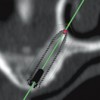
- 58. Platform Reduction and Etiology of Marginal Bone Loss around Implants Original Branemark design lost bone down to the first thread. Why?v Thread design?v Surface topography?v Conical implant seal?v Design of the neck?v Platform reduction? (switching)
- 59. Etiology of the initial bone loss around implantsv Almost immediately the original “Branemark” design lost bone down to the first thread.v Other designs such as the “Astra” design appear to retain their bone levelsv What is the evidence?What are the likely explanationsfor this difference?
- 60. Etiology of initial bone loss around implants Angulation of the neck v An implant is torqued into position with 45 Newtons v However, the torque values around the neck of the implant imbedded in the cortical bone is probably closer to 100 Newtons. v Will these values predispose to resorption to the cortical bone around the neck of the implant when the angle of the implant is acute?
- 61. Etiology of initial bone loss around implants v Angulation of the neck v Whenocclusal loads are applied will the implants with acute angles atop of the implant overload the bone in this area precipitating a resorptive remodeling response and bone loss?
- 62. Platform reduction (platform switching) Courtesy G. Perri Courtesy C. Stanfordv Note the bone levels atop the implant.v Is it the result of the horizontalization of the biologic width (platform reduction)?
- 63. Platform reduction (platform switching) Courtesy G. Perri Courtesy C. StanfordThe evidence is far from clear. v In these examples the angulation of the top of the implant may be the more important factor v In addition in both these implant systems the micro-rough surface was extended to the top of the implant. This also, may contribute to the maintenance of bone levels atop the implant.
- 64. Angulation of the neckv Some authors have maintained that the angulation atop the implant is the most important factor. (Braun, et al, 2006; Iacono et al , 2006)v They attribute the maintenance of bone atop of the implant to the so-called “negative” slope (dotted lines).
- 65. The presence of micro-threadsCourtesy G. Perri Courtesy C. Stanford Is it the result of the microthreads around the neck of the implant?
- 66. Internal interlocking vs external hex system Conical sealv Allabutment – implant fixture interfaces demonstrate gaps upon loading from 10-50 microns. The original external hex systems demonstrates the largest gaps during flexure.v Do these gaps harbor micro-organism which in turn precipitate an inflammatory response leading to bone loss around the neck of the implant?
- 67. Marginal Bone LossBased on a Med Line search, a review of the literatureindicated that no implant system, surface or designwas found superior with regards to marginal bone loss(Abrahamsson and Berhlundh, 2009)
- 68. Platform Switching (Reduction)Will this type of implant fixture – abutmentconfiguration minimize the bone loss around the neckof implants?v Basedon a review by Bateli and Strub (2011) “the current literatureprovides insufficient evidence about the effectiveness of any specificmodification in the implant neck area in preserving marginal bone orpreventing marginal bone loss”
- 69. One piece systemsNobel direct and similar one piece systems There are no gaps developing between an abutment and fixture. Why the bone loss? Most have modern surfaces. Many were immediately provisionalized and loaded with cement retained restorations. In many cases the cement extended down to the boney levels v Aninflammatory response was initiated which was progressive and irreversible leading to extensive bone loss.
- 70. Zirconium Implant Fixtures (Strub et al, 2010) v Has been promoted for use in the esthetic zone v Biocompatible ” Histology similar to titanium – about 60% bone implant contact area ” Anchorage is similar to titanium v Microrough surfaces the best v Success rates equivalent to titanium v UV exposure makes the surface more bioreactive v Fractures ” One piece system – fractures at ¼ the load compared to titanium ” Two piece systems fracture at 1/6th the load compared to titanium ” Alumina reinforced zirconium is strongerNot ready for clinical use. Some people believe that zirconiumimplants will eventually disappear from the market.
- 71. Zirconium abutments and frameworksUsed in the esthetic zone Abutments l Less plague adherence l More esthetic l Higher fracture rate Frameworks l High incidence of chipping of porcelain off the zirconium frameworks l Not recommended for posterior teeth Courtesy Dr. A. Sharma
- 72. v Visitffofr.org for hundreds of additional lectures on Complete Dentures, Implant Dentistry, Removable Partial Dentures, Esthetic Dentistry and Maxillofacial Prosthetics.v The lectures are free.v Our objective is to create the best and most comprehensive online programs of instruction in Prosthodontics
New Lectures
 Prosthodontic Procedures and Complications
John Beumer III DDS, MS
Robert Faulkner, DDS
Robert Faulkner, DDS
 Computer Guided Treatment Planning and Surgery
John Beumer III DDS, MS
Allesandro Pozzi, DDS
Robert Faulkner DDS
Allesandro Pozzi, DDS
Robert Faulkner DDS
 Implants and RPDs
John Beumer III DDS, MS
Ting Ling Chang DDS
Robert Faulkner DDS
Ting Ling Chang DDS
Robert Faulkner DDS
 Single Tooth Defects in Posterior Quadrants
John Beumer III DDS, MS
Robert Faulkner, DDS
Robert Faulkner, DDS